|
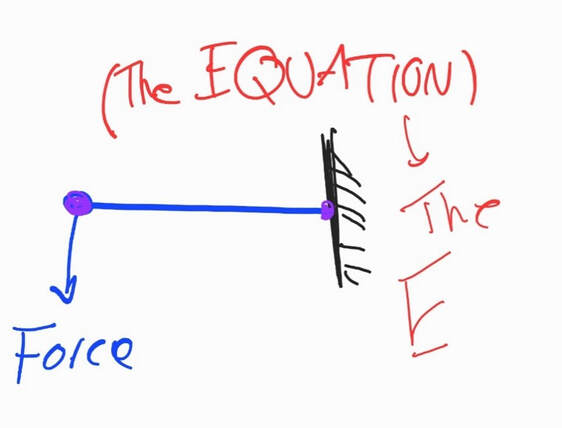
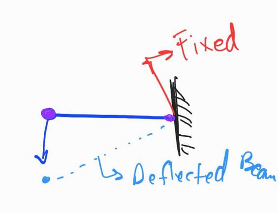
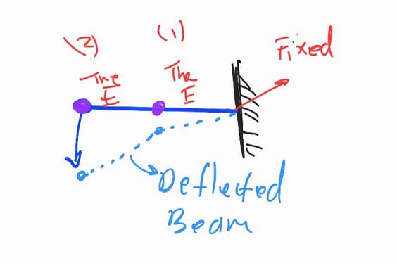
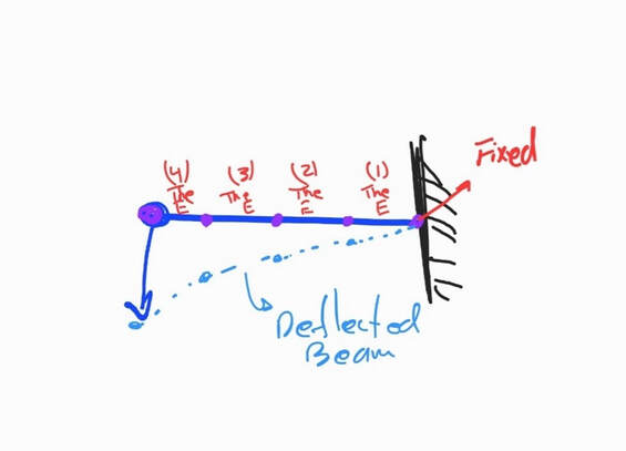
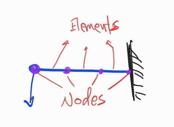
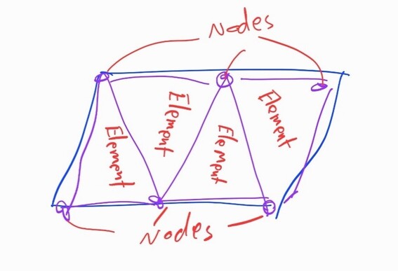
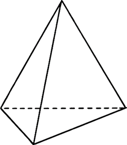
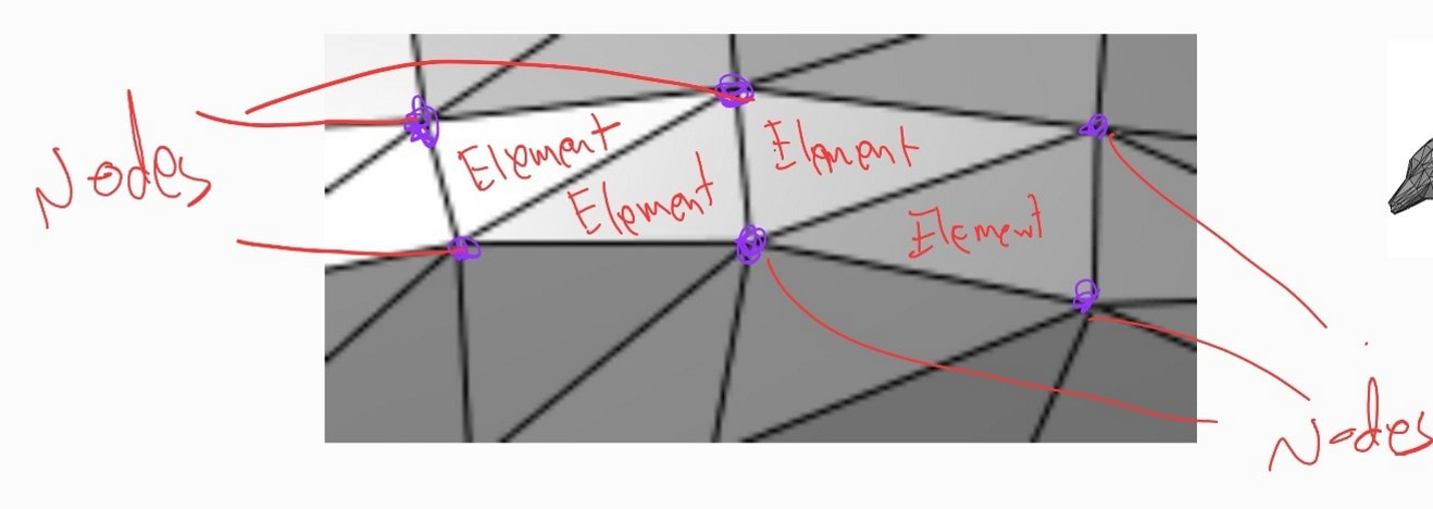
In this post, we will try to make sense of what is finite element analysis (FEA) and how it works without getting into talking about equations or much technical terms. SOLIDWORKS Simulation (and other software) uses FEA to solve designs. Thus, knowing a bit of background about FEA will help us understand many of the settings to optimize our results. To explain FEA in simple terms, we can try simplifying FEA with a story of the progression of the elements from one dimension to 3 dimensions. One Dimensional Beams:It all started with the classic problem of a beam. The beam is fixed on a wall from one end, and there is a force on the other end. Experts came together and made up an equation to find the deflection at the outer end. What the equation looked like is none of our concern for now, so we can just call it THE EQUATION. Here is what concerns us: To be able to calculate the deflection on the outer end, we had to know beforehand what the deflection is on the inner end connected to the wall. In this classic beam case, we know that the inner end is fixed to a wall. Thus, there is no deflection, or the deflection is zero. With that known to us, we can apply the equation and find the deflection. Now the question is: What if we want to know the deflection in the middle of the beam? To find this, we can split the beam into two and redo the whole calculation. We can start with the first half, in one end we know the deflection is zero, so we can apply THE EQUATION to find the deflection at the end of the first half. Then, we can move to the second half and apply the same equation. Again, we already know the deflection in one end because we just calculated It, then the equation will give us the other end. Finite Element Analysis is dividing a structure into a smaller, finite number of elements which we can analyze one by one, then putting all those elements together gives us an understanding of the whole structure. What if we want to know the deflection in every quarter of the beam? In this case, we can simply redo the same procedure the same way, splitting the beam into four parts. We can go the same approach every tenth of the beam, every twentieth, and so on. Now let us stop here for a second to name things, we can all those little beam divisions: ELEMENTS,, at the end of each element, there are points that we can call NODES. This approach we just used or described in analyzing our beam is Finite Element Analysis. It is dividing a structure into a smaller, finite number of elements which we can analyze one by one, then putting all those elements together gives us an understanding of the whole structure. Two Dimensional Shells / Surfaces:Just now, we were looking at a straight beam, which we were able to split into straight little elements of lines and nodes. The next step would be to go to two dimensions. We can call those shells or sheets. A shell is anything that is relatively thin and of uniform thickness. Those include the common structures of sheet metals. Sheet metals can take many different shapes and forms. Also, unlike one-dimensional beams, there is no ‘THE EQUATION’ to solve for deflections on complex formations. To go around this, we can simply split the whole sheet into many nodes and lines. However, now that we are working in 2 dimensions, our elements can’t be a line. So, we can switch the elements into something like a triangle. Now, we can split our sheet into little triangular elements. Each has three little lines and three nodes. Just like how we started with beams, we must know the actual solution values somewhere in the design because it is fixed or restrained to something else. From there, we solve for each little line and each little element until we can solve for the whole model. Basically, we transformed the whole shell into many small one-dimensional beams. The collection of all the elements together is called Mesh. The more elements we have, the more accurate our results will be, but also the more calculations we will have to do. 3-Dimensional Solid Objects:At this point, we can jump into 3-Dimensional objects. which can be complex-looking turbines, gears, casings, consumer products, etc. We can refer to those as SOLIDS. As solids can take many different shapes and forms, there is no ‘THE EQUATION’ for all kinds of irregular shapes. However, that is not a problem because we can just split the whole thing into small elements to end up with a bunch of nodes and lines. Our element shape this time will have to be 3-dimensional shape, like a Tetrahedral, which is the shape of elements used in a software like SOLIDWORKS. As always, with one location of the design is known to us, so we can use THE EQUATION to solve what is happening in the next nodes, and move from there to the rest of the model. Generally speaking, the more elements we have, the more nodes and lines we have, the more accurate our results can be, and the more work we will have to do to solve it. Summary:In a nutshell, Finite Element Analysis is the idea of splitting any model into smaller elements that we can solve one at a time, then putting all those elements together can give us a good understanding of what is happening in the whole model. The power of FEA is that it enables us to understand and simulate how a specific design reacts to different conditions regardless of how complex the design is. Throughout this post, we gave a bit of focus to analyzing deflections. However, the same approach applies to analyzing and understanding many other parameters like stress distribution, the factor of safety distribution, etc. This post does not represent a factual background on Finite Element Analysis and should not be taken as such. Rather, you can take it as a way to simplify our understanding of what Finite Element Analysis is all about. If you are looking to dive into the use of an FEA-based simulation tool like SOLIDWORKS simulation, you can check out SOLIDWORKS Simulation Associate course. By Tayseer Almattar, TforDesign FounderTayseer is the founder of TforDesign. He has a passion for learning design and making all learning digestible and exciting.
LinkedIn: https://www.linkedin.com/in/tayseer-almattar-design-innovation
1 Comment
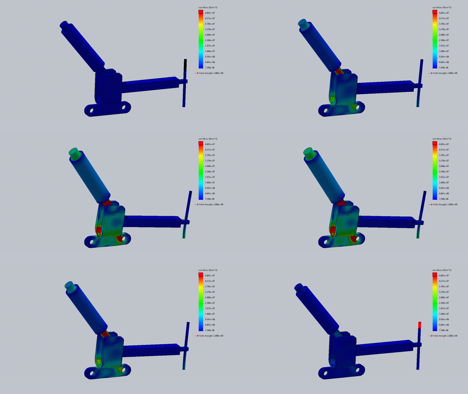
When asking about FEA simulations, you will likely find two groups of people: one calling it straightforward and easy and the other calling it complex and challenging. You will also find lots of young people sharing colored images and more experienced people talking equations and strange terms. What is behind all that? [it is not a cross-generational thing, at least I hope] Most of that comes from the introduction of software simulation tools. There is no doubt that Simulation tools, including SOLIDWORKS, Ansys, and others, brought in tremendous benefits and enhancements to simulation. However, they made simulation look super easy. But is it? So, let us try to break that further down to figure out some of the issues with the simulation software. First, one area to clarify is that most simulation studies are applied by following a similar overall procedure. You can check our previous blog on 8 steps to conducting FEA static studies for more information. Now, we did a simple study, let us talk about the complications. This blog will discuss the meaning behind the results, results verifications, and the overwhelming available options. What Do the Results Mean to Start With?Simulation software are famous for their colorful plots, usually ranging from red to blue, and accompanied by numbers. While it is easy to get numbers and plots, the more important question would be: what do those numbers even mean? Von Mises, stresses, strains, the factor of safety, stiffness, etc. More importantly, what do those numbers mean for us specifically in whatever project we are working on? How can they be used to drive/guide meaningful design iterations? Answering those questions would often require more in-depth knowledge and experience on topics that go beyond the apparent software application and into principles of design and mechanics of materials. Verdict:
Getting attractive and colorful plots can be pretty exciting when you start with simulation, but there is often more than meets the eye. How Do You Know the Software Gave You Correct Results?Perhaps one frequent and more challenging question you can get working with simulation is: How do you know you got usable/correct results? Simulation software nowadays are very capable; they are also growing rapidly. However, they are by no means a complete, accurate tool. Issues in results can be caused by anything from setting the simulation conditions wrong, software deficiency, to issues with our input to the software. Being able to spot those errors would often require both experience and depth of engineering knowledge. Some methods used to help can range from quickly spotting nonsensical results to benchmarking with hand calculations or other means. Verdict:
All the Options Out There!As simulation tools grow, so does the number of options they provide to help you get optimal results for your usage. Those include more variety in conditions setting, more options in refining the mesh, more plots, etc. Being able to navigate all those options to produce a usable study can range in difficulty according to the complexity of the study. The complexity comes from the number of options and having to understand what each option means in an absolute sense and what the option means to the specific study you are working in. For example, meshing refinement has several options, from setting a global mesh density to auto-adaptive meshing to manually adjusting the mesh in different areas of the design. Knowing about those options is the easy part compared to uniquely applying them to best fit each project. Verdict:
So, is Simulation Easy or Complex?All the writing above might have made you more confused than not. Is simulation easy or complex? The reality is simulation is just like other expanding fields of study. It has a surface, but beneath that exists a great depth. The deeper you go, the more complex things can get. Thus, do not be surprised when you meet people spending 20+ years using simulation and are still learning. While software applications came as great enablers for simulation, they can give some a false sense of knowledge, neglecting the depth of the field. Getting attractive and colorful plots can be pretty exciting when you start with simulation, but there is often more than meets the eye. Should I Learn Simulation?In terms of software application, a structured course can give you the best value for your time. You can check out the TforDesign SOLIDWORKS Simulation Associate course. This will build you a strong foundation in the practical software application using SOLIDWORKS. Another part is to equip yourself with a theoretical background in Mechanics of Materials and Finite Elements Analysis. Both fields are well-established in academia. Thus, browsing academic resources can give you the best value. When pursuing both directions, it is essential to know that growing in the area can take lots of time and patience. Are you a user of simulation tools? How was/is your experience? Let us know in the comment section. By Tayseer Almattar, TforDesign FounderTayseer is the founder of TforDesign. He has a passion for learning design and making all learning digestible and exciting.
LinkedIn: https://www.linkedin.com/in/tayseer-almattar-design-innovation If you ever wondered how to use the SOLIDWORKS simulation tools to conduct Static Finite Element Analysis, this blog is for you. This blog will explore what Finite Element Analysis Static studies are and how to do them in SOLIDWORKS. What are Static Studies/Analysis Simulations?Static Analysis Simulations are the most common and most basic type of analysis done in computerized tools like SOLIDWORKS Simulation. Another term for it is Static Equilibrium Simulation. They relate to bodies that are in an equilibrium state. In other words, the loads do not constantly change over time. Thus, most of the objects around us on an everyday basis can be simulated using static analysis. Those include chairs, desks, bottles, beam bridges, constructions, etc. To know more about the different types of simulation, why and who should use them, check out our article on What is Finite Element Analysis and why you should use it. How to Do a Static Analysis in SOLIDWORKS?Static simulations have a common uniform process that you can expect to repeat every time you conduct a new study on a part. Let us list those steps here and then apply them together in the SOLIDWORKS. The part's simulation procedure is as follows:
To see how those steps are applied and how to follow up with them, check out the following video: This is the procedure for parts simulations. When we simulate an assembly or a multi-body part, an extra step would be to identify to the software how each part interacts with the other. Do you have any experience with SOLIDWORKS Simulation? Share your experience with us in the comments. Suppose you are looking to get a deep dive into SOLIDWORKS Static Simulation. In that case, you can check out our SOLIDWORKS Simulation Associate Course, which will give you a strong foundation on the subject. By Tayseer Almattar, TforDesign FounderTayseer is the founder of TforDesign. He has a passion for learning design and making all learning digestible and exciting.
LinkedIn: https://www.linkedin.com/in/tayseer-almattar-design-innovation |
AuthorThe following blogs are written by TforDesign team and community members. Categories
All
|
© 2013 - 2024 TforDesign. All rights reserved.
Terms & Conditions | Privacy Policy | Cookie Policy | Sitemap
Terms & Conditions | Privacy Policy | Cookie Policy | Sitemap






 RSS Feed