|
In today's world, design and technology are increasingly intertwined, leading to more projects that combine the two. This convergence has created innovative fields that merge creativity with technical expertise, pushing the boundaries of what's possible. One field that showcases this blend is data visualisation, which has become a powerful tool for visually communicating complex information. However, to learn more about the topic, it's essential to understand the origins of data visualisation. Data visualisation has become a crucial skill within the broader field of data science, evolving from a complementary technique to an essential component of the data science toolkit. The growth of data visualisation in data science is supported by two key factors: the increasing quality and quantity of datasets and the advancement of technological platforms supporting visualisation. Although the history of data visualisation dates back centuries, early examples can be found in maps and astronomical charts. Then, a more modern form began in the 17th century when statistical data was first presented graphically. Since then, data visualisation has progressed significantly, adapting to new technologies and data types, specifically digital data, in recent years. As our digital world generates unprecedented volumes of data, effectively presenting this information has become critical across industries and disciplines. This has led to a surge in the popularity of data visualisation skills within the data science community, with professionals recognizing its importance in extracting and communicating meaningful insights from complex datasets. The Power of Visual Processing Besides the apparent supporting factors contributing to the growth of data visualisation, such as advancements in technology and the increasing quality of datasets, what makes visual data inherently a more exciting approach to presenting information? Visual information is significantly more straightforward to digest and consume than raw numbers or text. When data is presented visually, it often reveals more of the story hidden within the numbers. This is because our brains are wired to process visual information more quickly and efficiently according to MIT neuroscientists that found out that the brain can identify images seen for as little as 13 milliseconds. Data was being visualized by showing a list of connected items, their relationships, and the details within these connections. For example, the work of Barabási Lab in network science demonstrates how complex systems can be visualized by the “Hidden Patterns” exhibition. Their visualisations of social networks, biological systems, and technological networks have uncovered intricate relationships that were not apparent in the raw data. These visualisations allow researchers and viewers to grasp complex concepts and relationships at a glance.  “150 years of Nature” by Barabási Lab in the Hidden Pattern Exhibition visualising the connection of papers’ co-citation network The Art of Creating Compelling Visualisations Creating compelling data visualisations requires careful consideration of the targeted response from the audience. Choosing the correct type of visualisation for the data and the story you want to tell is essential. This involves understanding your audience, selecting appropriate mediums, and ensuring the visualisation is accurate and easy to interpret. The goal is to create a visual representation that presents the data, engages the viewer, and guides them toward the intended insights. Edward Tufte, a pioneer in data visualisation, emphasizes the importance of "graphical excellence," which involves presenting complex ideas with clarity, precision, and efficiency. His principles have guided many data scientists and designers in creating visualisations that are not only informative but also aesthetically pleasing. At its core, data visualisation is a form of storytelling. Artists like Refik Anadol and Aaron Koblin have pushed the boundaries of data visualisation, creating immersive and interactive experiences that tell compelling stories through data. Their work demonstrates how data visualisation can be both informative and emotionally engaging, turning abstract numbers into narratives that resonate with viewers on a personal level. For instance, Refik Anadol's "Melting Memories" project uses brainwave data to create stunning visual art, exploring the intersection of memory and technology. Aaron Koblin's "Flight Patterns" visualizes air traffic data, transforming mundane flight paths into mesmerizing patterns that highlight the complexity and beauty of global travel.  “Melting Memories” by Refik Anadol (2018) visualising the human neuro-mechanism  “Flight Pattern” by Aaron Koblin (2005) visualising the air traffic over North America
|


 |  |
By Grace Whitfield & Clayton Tsoi
Grace is a graphic designer and multimedia artist. She is enthusiastic about up-and-coming art technologies and emerging creative fields, like immersive installation art, UX/UI design, and virtual and augmented reality.
Clayton is an Electronic Engineer. He is passionate about problem-solving and improving API and software skills and aims to take on increasingly challenging projects while delivering effective solutions.
Linkedin (Grace): https://www.linkedin.com/in/grace-whitfield5/
Linkedin (Clayton): https://www.linkedin.com/in/claytontsoi/
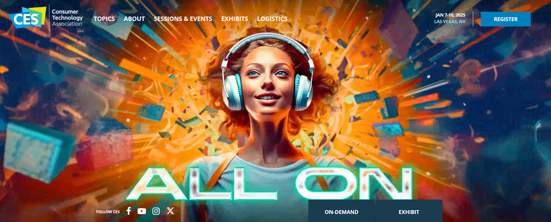
The Consumer Electronic Show (CES) 2024 stands as a pivotal platform not just for consumer technology exposure but also as a beacon for design innovation practitioners, businesses, and entrepreneurs as it demonstrates cutting-edge design elements and innovative product functionalities. It offers us insight into emerging tech trends, which we can use to draw inspiration, come up with new design strategies, and potentially collaborate across industries.
For businesses and entrepreneurs who attend the show, CES is a valuable opportunity for networking, brand visibility, and gauging market reactions to new products or concepts. It is a place where small startups can gain the same level of attention as tech giants, provided their contributions are innovative and compelling, making it a level playing field for all innovators. However, the conference has already passed, so we can look at what happened there to help us figure out what types of innovations are coming of interest in the coming years.
The event serves as a forecasting tool, helping businesses plan their product roadmaps and market entry strategies in line with the showcased tech trends. Entrepreneurs can use CES to identify niche markets and scope out competition. The CES is where market-leading ideas are born, and strategic alliances are formed, both of which are crucial for business growth and innovation in the tech industry.
By integrating these perspectives, CES 2024 transcends being merely a trade show; it is an invaluable resource for the entire technology ecosystem helping us understand the upcoming trends in both tech and culture.
In this article, we will try to form categories of what was presented in the show and show some interesting examples of each category. Our goal is not to provide a detailed analysis of the show, but rather to help you and ourselves understand the trends where tech is going and get inspired by some of the presented innovations. Looking at the CES 2024, we have concluded the following categories.
Now that we have our categories, let us dig into each one with a short description and some examples.
In this article, we will try to form categories of what was presented in the show and show some interesting examples of each category. Our goal is not to provide a detailed analysis of the show, but rather to help you and ourselves understand the trends where tech is going and get inspired by some of the presented innovations. Looking at the CES 2024, we have concluded the following categories.
- Display and Screen Technology
- Computing and Gaming
- Smart Home and Robotics
- Health Tech
- Audio and Entertainment
- Automotive and Mobility
- Smartphones and Wearables
- AI and Machine Learning Applications
- Sustainability in Tech
- Miscellaneous and Concept Innovations
Now that we have our categories, let us dig into each one with a short description and some examples.
Display and Screen Technology
Innovations revealed an emphasis on aesthetic and functional versatility in displays, including transparent OLED and Micro LED technology, as well as monitors and TVs with advanced features like high refresh rates and foldable designs, catering to both entertainment and professional needs. Here are some examples:
- LG Signature OLED T (LG) - A transparent OLED TV that appears to float in midair when the retractable contrast screen is down.
- UltraGear OLED Monitors (LG) - Gaming monitors that offer high refresh rates, quick response times, and features like Pixel Sound and immersive curves.
- Transparent Micro LED Display (Samsung) - A futuristic see-through display touted as a significant advancement over existing transparent screens.
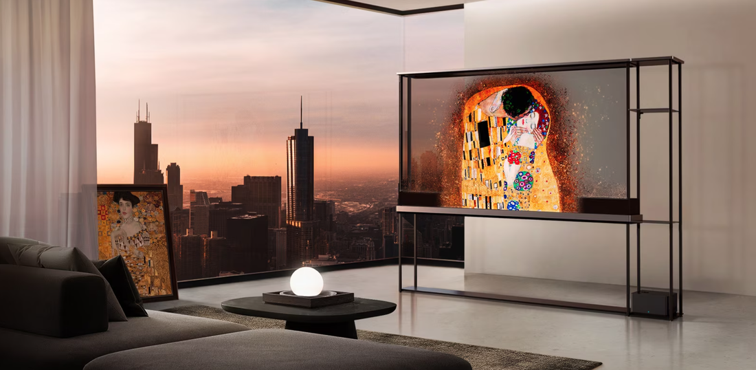
LG Signature OLED T
Computing and Gaming
CES 2024 showcased powerful and sleek laptops optimized for both gaming and portability, with impressive dual-screen designs, high-performance internals, and innovative form factors that redefine traditional computing experiences. Here are some examples:
- ASUS ROG Zephyrus G14 (ASUS) - A sophisticated, high-performance gaming laptop with aluminum chassis and customizable LED slash on the lid.
- Zenbook Duo (ASUS) - Two-screen laptop with a detachable keyboard, running on Intel's Core Ultra processors with OLED displays.
- ThinkBook Plus Gen 5 Hybrid (Lenovo) - A two-in-one laptop that runs Windows and Android simultaneously, catering to multitasking needs.
Smart Home and Robotics
The event highlighted the growing trend of integrating AI and automation into home appliances and robotics, with products that not only enhance convenience and efficiency but also provide assistance and companionship, pushing the boundaries of what's possible in household management. Here are some examples:
- AI Family Hub+ (Samsung) - A smart fridge with improved AI that can identify food, suggest recipes, and monitor expiration dates.
- Q Revo Max V (Roborock) - A robot vacuum with automated clean and dirty water tanks and hot water mopping capabilities.
- LG’s Latest Premium Smart Monitor Lineup (LG) - 4K IPS displays with built-in webOS for video streaming, chatting, and working without a PC.
Health Tech
Health-focused devices demonstrated a commitment to personal wellness monitoring and diagnostics, offering consumers more control over their health data through multi-functional, user-friendly gadgets designed for home use. Here are some examples:
- Bimo Multiscope (Withings) - A health device combining a body temperature sensor, ECG, oximeter, and digital stethoscope.
- Withings U-Scan (Withings) - A health-tracking device analyzing urine for various wellness and cycle markers.
- Adam X CPR Training Dummy (Medical X) - An anatomically precise medical training dummy that simulates multi-scenario patient responses.

U-Scan by Withings
Audio and Entertainment
CES 2024 introduced audio and visual entertainment advancements, including speakers that double as art installations and immersive personal listening experiences, all aimed at enriching the multisensory enjoyment of consumers. Here are some examples:
- Samsung Music Frame (Samsung) - A wireless speaker disguised as art or album cover display, supporting Dolby Atmos.
- Esther Sound Chair (Razer)- A chair with multiple built-in speakers creating an immersive sound experience with noise-dampening materials.
- One by One Music (One by One) - An AI trained to create comforting music for dogs with separation anxiety.
Automotive and Mobility
The automotive sector at CES 2024 spotlighted the future of transportation with solar-powered and electric vehicles, featuring cutting-edge autonomous driving tech and integrations that promise eco-friendly and efficient mobility solutions. Here are some examples:
- Squad Solar Buggy (Squad) - A self-charging solar-powered vehicle that is compact and designed for urban mobility.
- Aptera Solar Electric Vehicle (Aptera) - A highly energy-efficient solar-powered car that rarely needs charging.
- Vision-S 02 (Sony) - An electric SUV concept with high-level autonomous driving technology and an infotainment system.
Smartphones and Wearables
The smartphone and wearables segment featured devices that blend style with smart technology, such as foldable phones and sunglasses with electronic tint adjustment, indicating a melding of fashion with high functionality. Here are some examples:
- Flex In & Out Flip Concept (Samsung) - A smartphone prototype that can fold in both directions, forward and backward.
- Air Vision M1 Smart Glasses (Asus) - A pair of glasses designed to provide efficient multitasking with AR capabilities.

Air Vision M1 Smart Glasses from Asus
AI and Machine Learning Applications
CES 2024 displayed AI's further incorporation into everyday products, improving user interfaces, personalizing experiences, and introducing human-like interactions, reflecting the pervasive influence of AI across various tech sectors. Here are some examples:
- R1 AI Voice Assistant (Rabbit AI) - A voice assistant device with a "large action model" aiming to simulate a human-like interaction.
- Nvidia Omniverse Avatar Cloud Engine (ACE): An advanced platform that powers virtual assistants and digital humans, providing diverse AI services and capabilities for real-time interactive experiences across various industries.
- GyroGlove (GyroGear) - A glove using gyroscopes to stabilize hand movements for people with hand tremors.
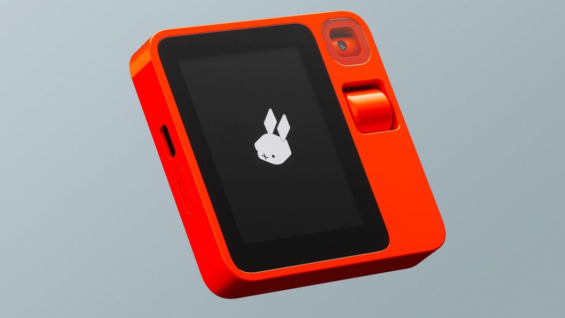
R1 AI voice assistant from Rabbit AI
Sustainability in Tech
Products presented a commitment to environmental responsibility, showcasing energy-efficient solutions and eco-friendly tech alternatives that align with the increasing demand for sustainable lifestyle choices. Here are some examples:
- Delta Pro Ultra (EcoFlow) - A hybrid solar generator capable of powering major home appliances using solar panels, the grid, or a gas generator.
- 100% Electric Grill by Char-Broil (Char-Broil) - An electric grill that reaches high temperatures for perfect searing without using gas or charcoal.
- Sonic MagFlow Fans (SE Sonic) - Daisy-chainable fans for PC builds that reduce cable clutter and simplify installations.
Miscellaneous and Concept Innovations
This category comprised an eclectic mix of tech, from innovative smart locks employing biometric security to whimsical concept gadgets, demonstrating CES's role as a playground for showcasing the most imaginative and sometimes unconventional ideas in tech. Here are some examples:
- Intelligent Door Locks with Facial Recognition (Lockly) - Smart door locks that grant access based on recognized facial data.
- CineBeam Cube Projector (LG) - A portable projector with a unique design capable of displaying large, vibrant images.
- Clicks Keyboard Case for iPhone (Clicks) - A case with a retro-inspired physical keyboard extending iPhone functionality with tactile typing experience.

Clicks Keyboard case for iPhone
As we reflect on CES 2024, it's evident that the event serves as an incredible window into the collective efforts and secret projects of tech innovators worldwide. It reveals the exciting direction technology is headed, spotlighting new trends and carving out opportunities for us to engage with. From seeing how our homes could become smarter to imagining cars that help the planet, and devices that blend seamlessly into our lifestyle, CES allows us to identify where we might go next. It's not just about witnessing the future unfold; it's about discovering paths we can take and opportunities we might seize. CES is where we get to see what's around the corner and start thinking about how we can be a part of the next big thing.

By Tayseer Almattar
Tayseer is a passionate designer and educator. He believes that innovation potential can be grown and nurtured within organizations with relevant design innovation processes.
LinkedIn: https://www.linkedin.com/in/tayseer-almattar-design-innovation
Tayseer is a passionate designer and educator. He believes that innovation potential can be grown and nurtured within organizations with relevant design innovation processes.
LinkedIn: https://www.linkedin.com/in/tayseer-almattar-design-innovation
Decoding COP 28: A Comprehensive Analysis and Its Implication for Business and Climate Action
12/25/2023
Introduction
The 28th Conference of the Parties, or COP 28, has just concluded on December 12th. What was that and what is it about? We'll explore all of this in this article.
COP 28 represents a milestone in the ongoing global effort to combat climate change. This pivotal UN conference is not just a gathering of political leaders, but also a ground-breaking platform to engage non-party stakeholders, including businesses, cities, investors, and even civil societies, in the mutual pursuit of decarbonization. It is a yearly conference and is hosted in a different country every year.
At its core, COP 28 aimed to facilitate actionable climate strategies by fostering open dialogue between various major actors, effectively closing the gap between rhetoric and action on a global scale. This inclusive approach emphasizes the high stakes of climate change and underscores the undeniable truth that its impacts are not confined to borders, and thus, no entity, be it a business or a city, is a mere bystander.
Integral to COP 28's mission is the Global Climate Action Agenda, which has been pivotal in galvanizing worldwide commitment toward mitigation, adaptation, and finance goals set by the Paris Agreement (from COP 21). This unique initiative is instrumental in sustaining momentum between COPs, showcasing real-world examples of climate solutions, and mobilizing diverse sectors of society in driving global ambition and action against climate change.
Ultimately, COP 28 and the Global Climate Action Agenda symbolize our collective pursuit to create a sustainable future.

Outcomes of COP 28
Even though COPs started with a focus on climate, their scope keeps expanding with our understanding that addressing the climate issue is also related to other social and economic issues. COP 28 had four strategic pillars as identified by the conference presidency. Here is a close look at each of them and their implications.
- Energy Transition: At COP 28, a renewed emphasis was placed on accelerating the global transition towards a more sustainable energy future. Discussions were centered around how to facilitate a shift that is not only swift but also gradual and equitable, to ensure that no community or country is left behind. Notably, attention was brought to novel technologies and innovative strategies that can pave the way for a holistic and clean energy landscape. While the specific announcements were wide-ranging, they all underscored the importance of an efficient and effective global energy transition.
- Climate Finance: Another key focus at COP 28 was to streamline climate finance, a critical aspect for implementing broad-ranging climate action plans. The conference explored various strategies aimed at increasing financial flows toward climate-friendly initiatives and ensuring accountability for climate-related expenditures. Some of the significant announcements during this session revolved around bridging the gap between developed and developing nations and driving climate investments in a way that is transparent, accessible, and efficient.
- People, Lives, and Livelihoods: Underpinning the discussions at COP 28 was a strong commitment to prioritize people, their lives, and their livelihoods in all climate actions. Tangible steps were proposed to safeguard the most vulnerable from adverse climate impacts, with an understanding that the struggle against climate change is fundamentally a struggle for a better, more secure world for all. The conference called for solutions that interweave the fight against climate change with efforts to uplift communities, enhance livelihoods, and promote human well-being.
- Inclusivity: Perhaps the most defining characteristic of COP 28 was its dedication to ensuring full inclusivity. Recognizing the need for diversified perspectives in crafting comprehensive solutions, a wide variety of non-party stakeholders were welcomed to both contribute to and influence discussions. This commitment helped ensure every decision, action, and initiative was underscored with a spirit of inclusivity, reiterating the vital insight that the path to a sustainable future must be walked together.
Pledges, Declarations, and Joint Statements
In the context of the COP, pledges and declarations play a crucial role in setting commitments and intentions by countries and stakeholders to address climate change. These pledges and declarations serve as crucial signals that reveal nations' determination to act on the climate crisis, despite not necessarily being legally binding.
The significance of pledges and declarations lies in their potential to catalyze momentum, inspire innovation, and instigate peer pressure to drive climate action. They signal a collective resolve to engage in comprehensive climate mitigation and adaptation, which could lead to enhanced collaboration and sharing of best practices between different countries. Further, they have the potential to attract investments in clean technology and catalyze new collaborative platforms that support climate action implementation.
However, the effectiveness of pledges and declarations ultimately depends on national implementation and enforcement mechanisms. To ensure that they deliver tangible results, it is essential to track progress, frequently update goals, and maintain transparency around implementation.
- Pledges: In the context of COP, these are specific commitments made by countries and stakeholders to achieve certain goals or take specific actions, expressing their aspirations or promises.
- Declarations: Formal statements by a country or group of countries that highlight their intentions or guiding principles for action in addressing climate change.
- Joint Statements: Collective agreements or commitments made by multiple countries or entities during a COP conference, reflecting common understanding, recognition, or concern about particular climate-related issues.
The significance of pledges and declarations lies in their potential to catalyze momentum, inspire innovation, and instigate peer pressure to drive climate action. They signal a collective resolve to engage in comprehensive climate mitigation and adaptation, which could lead to enhanced collaboration and sharing of best practices between different countries. Further, they have the potential to attract investments in clean technology and catalyze new collaborative platforms that support climate action implementation.
However, the effectiveness of pledges and declarations ultimately depends on national implementation and enforcement mechanisms. To ensure that they deliver tangible results, it is essential to track progress, frequently update goals, and maintain transparency around implementation.

Part of the International governmental delegation attending COP 28.
Selected examples of pledges, declarations, and joint statements
You might be wondering what those pledges, declarations, and joint statements look like. Below are selected examples of those and what each entails.
These are some examples of how various countries and stakeholders worldwide are taking steps towards addressing climate change on multiple fronts.
- Global Renewables and Energy Efficiency Pledge: This pledge involves Heads of State and governments committing to increase the deployment of renewables and energy efficiency as strategies to achieve the Paris Agreement goal, with targets including tripling renewable energy capacity by 2030 and doubling global energy efficiency improvements annually until 2030.
- COP28 UAE Declaration on Climate and Health: Recognizing the interconnections between health and climate, 141 national governments pledged to advance climate-resilient development, strengthen health systems, and build resilient communities for the present and future generations.
- COP28 UAE Declaration on Sustainable Agriculture, Resilient Food Systems, and Climate Action: Signed by 153 national governments, the declaration highlights the urgency of building a climate-resilient food system and commits to actions such as reducing the vulnerability of farmers and promoting food security and nutrition.
- Joint Statement on Climate, Nature, and People: Eighteen national governments committed to collaborative action for climate and nature protection, further reaffirmed by the participation of 150 non-party stakeholders in the Nature Positive for Climate Action Call.
- UAE Leaders’ Declaration on a Global Climate Finance Framework: This declaration was endorsed by 13 national governments to establish a global climate finance framework, emphasizing the need for a significant mobilization of public and private finance to address climate change.
- COP28 Gender-Responsive Just Transitions and Climate Action Partnership: This partnership invokes the inclusion of gender-responsive strategies and emphasizes equitable and fair transitions in climate action, recognizing the different impacts of and responses to climate change based on gender.
These are some examples of how various countries and stakeholders worldwide are taking steps towards addressing climate change on multiple fronts.

How about you as an entrepreneur or a business
One of the best ways that entrepreneurs and businesses can capitalize on COP 28 is to use the outcomes as a guide or a factor in their next endeavors and/or strategic directions. Above all, the COP outcomes can indicate what many future promising opportunities entail. Here are some examples that can be inferred from COP 28 outcomes.
By understanding and acting on COP28's outcomes, you can position yourself favorably for the low-carbon economy on the horizon.
- Adopting Sustainability: Businesses can invest in sustainable practices to align with the global consensus from the conference. This could involve sustainability in operations such as manufacturing, sourcing, packaging, product design etc. By adopting sustainable practices businesses can create brand value and attract conscious customers.
- Leveraging Economic Incentives: Many pledges and initiatives announced at COP28 involve financial incentives for reducing carbon emissions and adopting cleaner technologies. Hence, companies have a direct economic incentive to get involved in green entrepreneurship and sustainable business practices.
- Innovation and New Technologies: With the heightened interest in clean technology demonstrated at COP28, there is a wealth of opportunities for entrepreneurs and businesses to innovate and provide new solutions. Whether in renewable energy, energy efficiency, carbon capture, electric vehicles, or other areas, the demand is set to increase.
- Strategic Partnerships: COP28's outcomes often foster collaborations between governments, corporations, and NGOs. Private sector companies can partner with these entities to align their CSR strategies, access funding, and better position their brand.
- Investor Engagement: COP28 draws attention to climate risk and encourages investors to firmly integrate ESG (Environmental, Social, Governance) considerations into their portfolios. Businesses showcasing strong climate commitments and sustainable practices are more likely to attract such investors, and thus secure better financing.
By understanding and acting on COP28's outcomes, you can position yourself favorably for the low-carbon economy on the horizon.
More info
If you are looking for more information about COP 28, you can check out the official website for the conference here: https://www.cop28.com/en/
If you would like to know more about Climate Change which is also the cause for all the COP conferences, you can check out our Climate Change Course on the TforDesign Platform. You can also find the course on Udemy.
P.S. Here is a little inspirational video about the event published by COP28 UAE:
If you would like to know more about Climate Change which is also the cause for all the COP conferences, you can check out our Climate Change Course on the TforDesign Platform. You can also find the course on Udemy.
P.S. Here is a little inspirational video about the event published by COP28 UAE:

By Tayseer Almattar
Tayseer is a passionate designer and educator. He believes that innovation potential can be grown and nurtured within organizations with relevant design innovation processes.
LinkedIn: https://www.linkedin.com/in/tayseer-almattar-design-innovation
Tayseer is a passionate designer and educator. He believes that innovation potential can be grown and nurtured within organizations with relevant design innovation processes.
LinkedIn: https://www.linkedin.com/in/tayseer-almattar-design-innovation
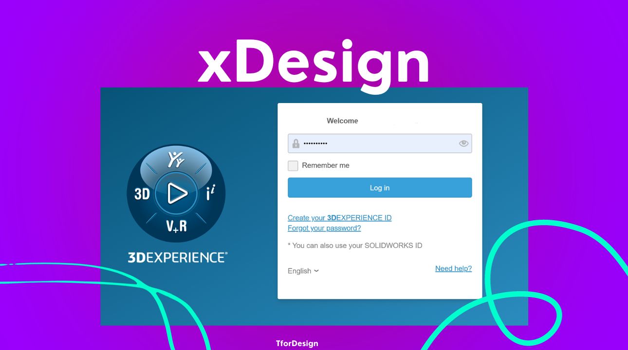
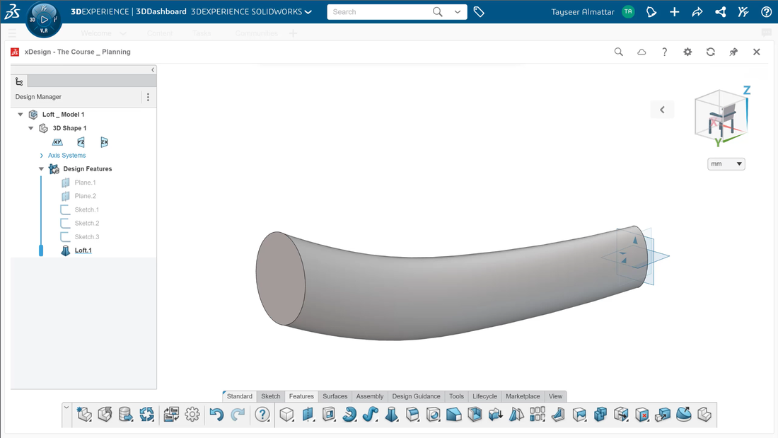
xDesign is a 3D modeling and design tool that is part of Dassault Systèmes' 3DEXPERIENCE platform. It allows users to create and collaborate on 3D designs through a web browser without needing to install any specialized software or hardware. Many people refer to xDesign as SOLIDWORKS Cloud or as an integrated part of the SOLIDWORKS cloud endeavor.
Key Capabilities of xDesign
Before we delve into discussing xDesign, as a tool, let us talk about its key capabilities and advantages. After all, those would decide if you want to invest in learning the software. Some of the standout capabilities of xDesign include:
- Cloud-based: Enables access from any internet-connected device like PCs, Macs, tablets and smartphones. Being a cloud-based software means you won't have to worry much about the capability of your device to handle the software.
- Real-time collaboration: Allows teams to work on 3D designs simultaneously. Thanks to it being on the cloud, xDesign allows multiple users to share, edit, and develop the same files concurrently.
- The 3DExperience platform: A major advantage of xDesign is it is part of the 3DExperience platform by Dassault Systèmes. This means easy integration with tons of other tools facilitating communication, management, simulation, etc.
How to Access xDesign
xDesign, being a part of the 3D Creator rule within the 3DEXPERIENCE platform. Here are a few ways in which you can access it:
- The 3D Creator Role: A direct avenue to xDesign, the 3D creator role lets you acquire this tool as a standalone solution.
- 3D Designer for Educators: xDesign is an integral part of this package, specifically for educators keen on using technology to shape future designers.
- SOLIDWORKS Cloud Apps for Students: Students eager to dive into the world of 3D design can easily access xDesign through the SOLIDWORKS Cloud Apps package.
- 3D Experience SOLIDWORKS for Makers: This offering caters to makers and hobbyists by including xDesign in its suite of tools, thereby facilitating the design of DIY projects.
In summary, XDesign provides a flexible, collaborative approach to 3D design through its cloud-based architecture. By emphasizing accessibility and real-time teamwork, it aims to simplify and streamline 3D modeling.
How to Learn xDesign?
xDesign carries many similarities with other 3D design tools like SOLIDWORKS, CATIA, Fusion 360, and others. If you know know to use those other tools, then getting up to speed with xDesign will not be an issue.
If you would like to follow a structured program, check out our xDesign: become a Certified Associate Today program. The program covers the essentials of the tool and helps you get up and running with xDesign for your 3D modeling needs.
If you would like to follow a structured program, check out our xDesign: become a Certified Associate Today program. The program covers the essentials of the tool and helps you get up and running with xDesign for your 3D modeling needs.
By Tayseer Almattar
Tayseer is a passionate designer and educator. He believes that innovation potential can be grown and nurtured within organizations with relevant design innovation processes.
LinkedIn: https://www.linkedin.com/in/tayseer-almattar-design-innovation
Tayseer is a passionate designer and educator. He believes that innovation potential can be grown and nurtured within organizations with relevant design innovation processes.
LinkedIn: https://www.linkedin.com/in/tayseer-almattar-design-innovation
Imagine an operating system specifically tailored for product design and development. It contains a suite of integrated apps for tasks like CAD modeling, simulation, project management, and data analytics. This is the vision behind Dassault Systèmes’ 3DEXPERIENCE Platform - a unified digital workspace aiming to transform how products are designed, tested, and manufactured. However, as you can guess, executing such an ambitious vision comes with very real challenges.
A Revolutionary Vision
You can picture the 3DEXPERIENCE Platform as an operating system with various apps for design, management, communication, and more. Then, depending on the rules of the person, s/he will be assigned different rules and access different apps in the system. By housing these apps together, they can integrate seamlessly to streamline workflows. Dassault Systèmes aims to break down silos, enable global teams to collaborate, and ultimately drive business innovation. However, any visionary idea inevitably faces bumps on the road to widespread adoption.
Initial Promise
During my exploration of the platform, the demos showcased its potential - seamless communication, accelerated design cycles, and predictive analytics. On the surface, it could significantly improve digital workflows. However, for organizations used to existing systems, migrating to a new platform can require a monumental change in both mindsets and practices.
The 3DEXPERIENCE Platform promises several impressive capabilities to cater to the diverse needs of businesses. These include:
The 3DEXPERIENCE Platform promises several impressive capabilities to cater to the diverse needs of businesses. These include:
- Global Connection - With this platform, you can link up and collaborate with colleagues around the world in real time. No more coordination headaches or playing phone tag across time zones. It makes it smooth sailing to brainstorm ideas and work together from wherever you are.
- All-In-One Access - The platform brings together a killer suite of design, engineering, and manufacturing apps that are connected together with cloud tools. Those include desktop apps like SOLIDWORKS and CATIA in addition to cloud design tools like xDesign and xShape. This facilitates design tracking and collaboration as everything is in one place.
- Efficient Monitoring - Keeping tabs on projects and data can be a major pain. But with the platform's dashboards and reporting features, overseeing your workflows is simple. You've got the visibility you need to manage projects and monitor progress easily.
- Informed Decision-Making - With serious analytics and simulation power, the platform helps you model different scenarios before locking in strategic decisions. You can predict the implications and minimize risks, allowing you to optimize resources and maximize results. No more shooting in the dark.

Monumental Scope
While Dassault has impressive design tools, connecting them into one unified ecosystem is enormously complex. Integrating global teams with different languages and time zones is difficult enough without building an intuitive workspace for the entire product lifecycle.
The scope of Dassault's vision is massive - to fully unite design, collaboration, data analytics, and more into a single platform. Transforming standalone tools into an all-encompassing system remains an ambitious goal.
The scope of Dassault's vision is massive - to fully unite design, collaboration, data analytics, and more into a single platform. Transforming standalone tools into an all-encompassing system remains an ambitious goal.

Cautious Optimism
The 3DEXPERIENCE Platform shows promise but still needs time to entice organizations to get on board. This is in addition to the massive development needed to improve the platform from its initial stages. While skepticism persists, my hope is that Dassault could gradually overcome challenges to bring this vision to life - one step at a time. With a thoughtful rollout, this revolutionary concept may slowly transform digital workflows in the years ahead.
Extra note:
If you want to get started with a look into the 3DExperince Platform, particularly the 3D Creator rule and the xDesign app, then we have a program just for that. You can check it out here.
Extra note:
If you want to get started with a look into the 3DExperince Platform, particularly the 3D Creator rule and the xDesign app, then we have a program just for that. You can check it out here.
By Tayseer Almattar
Tayseer is a passionate designer and educator. He believes that innovation potential can be grown and nurtured within organizations with relevant design innovation processes.
LinkedIn: https://www.linkedin.com/in/tayseer-almattar-design-innovation
Tayseer is a passionate designer and educator. He believes that innovation potential can be grown and nurtured within organizations with relevant design innovation processes.
LinkedIn: https://www.linkedin.com/in/tayseer-almattar-design-innovation
Have you ever imagined how artificial intelligence (AI) like chatGPT could revolutionize 3D modeling? Imagine using simple English to model complex video game environments or engineer a high-precision machine part. That would be fascinating, right?
Although this is not the reality right now, let's discuss some things we can expect to happen soon
Although this is not the reality right now, let's discuss some things we can expect to happen soon
3D Modeling and AI
First, let's acknowledge that 3D Models can be broken into code. ChatGPT and other language models, on the other hand, can write code. So theoretically, ChatGPT could generate 3D models as well.
In this article, I'll touch on different parts of the 3D model spectrum: Art on one end, Engineering on the other, and Product Design somewhere in between.
In this article, I'll touch on different parts of the 3D model spectrum: Art on one end, Engineering on the other, and Product Design somewhere in between.
Art in 3D Modeling
Art in 3D modeling cares most about the external shape of models, for example, creating video game assets or virtual replications of specific places. In these contexts, specific dimensions, mechanisms, and minor details might not hold significant value.
With AI, I foresee a significant impact on this area. Instead of manually building or modifying objects in a game environment, you could use natural language to create those things like image generation engines like mid-journey and DALLE. A key feature of these recent AI models is the inherent randomness in output execution, which is acceptable in many art-based applications.
With AI, I foresee a significant impact on this area. Instead of manually building or modifying objects in a game environment, you could use natural language to create those things like image generation engines like mid-journey and DALLE. A key feature of these recent AI models is the inherent randomness in output execution, which is acceptable in many art-based applications.

Engineering in 3D Modeling
The inherent generative AI randomness might not be well suited for Engineering. In this field, models must serve a function and be precisely detailed to be manufacturable, making typing "Design a car engine" and getting a functioning design less feasible. However, AI will enhance two main areas:
- Generative or Assistive Design: Designers can provide certain parameters, and the AI system drafts a design accordingly. For example, when designing a frame for a crane, you can provide specifications like size and anticipated stress levels in different areas, and the software will produce a design adhering to these parameters.
- Automation: Designers can build a base model and alter it into various versions using natural language prompts, creating a user-friendly experience for non-tech-savvy individuals and enabling mass customization simultaneously.

Product Design and AI
Product designers can benefit from everything mentioned earlier. In fact, they can already use existing image generation models like Mid-Journey and DALL'E to generate quick design inspirations or even generate orthogonal views for tracing in 3D software.
Implications
Overall, with all those taking place, what is the AI's impact on 3D modeling that can impact us? Those can be seen in two clear areas:
- Efficiency: AI's potential to increase efficiency with assistive design and automation is extremely promising. This will result in fewer people being able to do more work.
- Bridging the Expertise Gap: AI tools like assistive design alongside other technologies will enable designers and engineers with mid-level expertise to contribute more to areas formerly dominated by senior personnel.
Final Thoughts
While many people are making a devil of AI due to the possibility of it replacing the workforce, the situation is quite complex. In general, Automation and computers have been impacting the design fields for many years. This goes from paper-based drawing boards to today's complex 3D design software. The recent generative AI rise is no different.
One of the best ways to keep an edge in this age is to keep on learning and honing your skills while monitoring the evolution of technology and its impact on the field. If you are already good at 3D modeling, you will naturally have an edge in using emerging technologies to evolve your existing work.
It is still a good time to start learning a 3D design tool like SOLIDWORKS. You can check our TforDesign school for learning programs on 3D modeling. You can also subscribe to our social media channels linked at the footer, which will keep you updated on all the new advancements, and how they can impact you.
Feel free to get in touch with us for ways we can help.
By Tayseer Almattar
Tayseer is a passionate designer and educator. He believes that innovation potential can be grown and nurtured within organizations with relevant design innovation processes.
LinkedIn: https://www.linkedin.com/in/tayseer-almattar-design-innovation
LinkedIn: https://www.linkedin.com/in/tayseer-almattar-design-innovation
On 20 March, 2023, the Intergovernmental Panel on Climate Change (IPCC) report came out. The IPCC's Sixth Assessment Report (AR6) Synthesis Report assesses the current state of knowledge on climate change, its widespread impacts and risks, and opportunities for scaling up effective action in the period up to 2040. The report itself can provide good guidelines for our next business design endeavor.
We'll link the full report below. However, here is a little selection of some of the major points highlighted in the report.
We'll link the full report below. However, here is a little selection of some of the major points highlighted in the report.
First: Earth's temperature has increased by approximately 1.1°C (or 1.9°F) since pre-industrial times. The report outlines that the 1.5°C limit is still achievable. We discussed this point and how it came about in the Paris Agreement in our climate change course.
Now, let us look into 10 other points addressed in the report:
1. The report acknowledges the interdependence of the climate, ecosystems, biodiversity, and human societies as well as the importance of various knowledge modalities. So, the issue of climate change is not just one of the environment. It is a societal problem that must be solved with a wide range of knowledge and skills.
2. The report identifies instances of transformational action that are efficient, doable, equitable, and just. Accordingly, the report acknowledges the need for bold climate action to achieve significant reductions in greenhouse gas emissions while being implementable and practical. A crucial point is that actions shouldn't disproportionately harm marginalized groups or exacerbate already existing inequalities.
3. In every region of the world, human-caused climate change is already having an impact on numerous weather and climate extremes. This indicates that the effects of climate change are already being felt on a global scale and are not just a threat to the future. In-depth information about how climate change is affecting various areas and industries, including agriculture, health, and water resources, is provided in the report.
4. In order to keep global warming to 1.5°C and prepare for the effects of climate change, urgent and ambitious action is required. This indicates that the report strongly emphasizes the necessity of acting quickly to meet the Paris Agreement's most ambitious goal of limiting global warming to 1.5°C. The need for adaptation measures to assist communities and ecosystems in coping with the effects of climate change that are already present is also highlighted in the report.

5. The report emphasizes the connections between sustainable development, ecosystem health, human well-being, and climate change adaptation and mitigation. This indicates that the report acknowledges the necessity of addressing climate change holistically and comprehensively, taking into account the numerous advantages and drawbacks of various climate solutions. For instance, preserving and restoring ecosystems can support biodiversity, human well-being, and climate change mitigation.
6. According to the report, global warming of 1.5 degrees Celsius or more will cause increasingly severe and frequent climate impacts, such as more frequent heatwaves, heavy precipitation events, and more intense tropical cyclones, which will further alter the planet we are accustomed to.
7. The report emphasizes the dangers of passing crucial tipping points, including the irreversible melting of glaciers and ice sheets and the disintegration of some ecosystems.
8. The report points to opportunities for radical change in how we use energy, manage our land, plan our cities, and build our infrastructure, all of which can help with climate mitigation and adaptation. This means that the report emphasizes the necessity of switching to sustainable and low-carbon development pathways as well as the potential for transformational change in various economic sectors.

9. The report acknowledges significant challenges to achieving transformative change, including technological, economic, social, and political factors, entrenched interests, and power imbalances.
10. The report emphasizes the importance of international cooperation and effective governance mechanisms to support climate action at all local and global levels.
What do you think of the following points? Anything you would like us to elaborate more on? Or do you think they are all a repeat of what everyone knows already?
Here are the links if you would like to learn more:
- Link to all the report elements: https://www.ipcc.ch/report/ar6/syr/
- Link to the longer written report: https://report.ipcc.ch/ar6syr/pdf/IPCC_AR6_SYR_LongerReport.pdf
By Tayseer Almattar and Copyai
Tayseer is a passionate designer and educator. He believes that innovation potential can be grown and nurtured within organizations with relevant design innovation processes.
LinkedIn: https://www.linkedin.com/in/tayseer-almattar-design-innovation
LinkedIn: https://www.linkedin.com/in/tayseer-almattar-design-innovation
Why is Project-Based Learning Needed?
Learning something new, like 3D modeling, appears to be straightforward: you can use an extruded boss to get a cube and a revolved boss to get a sphere. But it is not this simple while modeling a real-life object, e.g., a car. Of course, modeling a car will require basic commands like extrude and revolve, but when and how to apply them is a whole new ball game. That is why when you go on 3D modeling real-life objects, a lot of challenges arise.
This leads us to project-based learning (PBL), which is more successful than traditional classroom-based learning. So, what is project-based learning, and how can it assist you in learning a skill like 3D modeling using SOLIDWORKS?
This leads us to project-based learning (PBL), which is more successful than traditional classroom-based learning. So, what is project-based learning, and how can it assist you in learning a skill like 3D modeling using SOLIDWORKS?
What is Project-Based Learning?
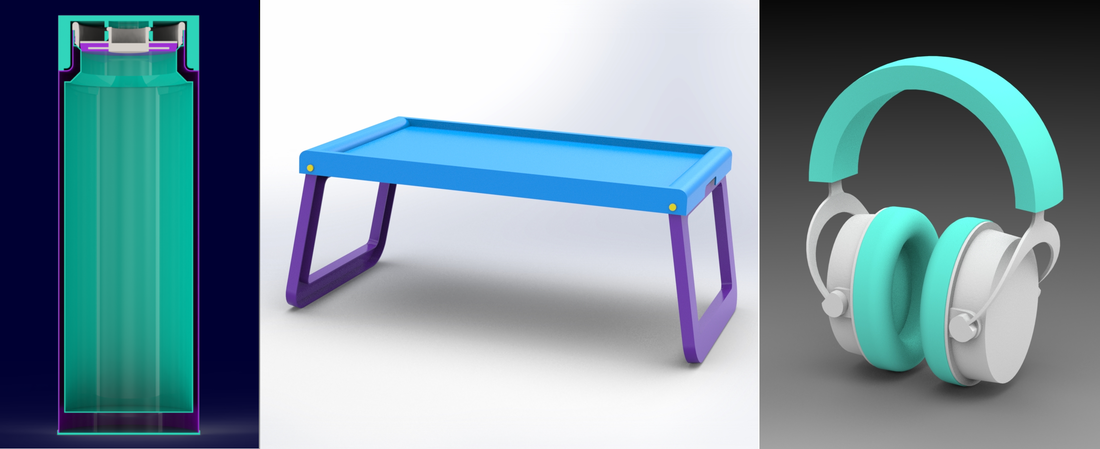
Project-based learning, also referred to as “learning by doing”, develops knowledge and skills by engaging in meaningful projects based on real-life challenges and problems. In the case of 3D modeling, these projects can be the objects around you, like a water bottle, folding tray, headset, etc.
While working on these projects, you will not only learn SOLIDWORKS (which is your desired goal) but also develop critical thinking, creativity, perseverance, and self-confidence. This will also ensure that you retain the learned concepts and modeling skills for longer.
Applying Project-Based Learning with SOLIDWORKS
Let’s assume that you want to model the following headset.
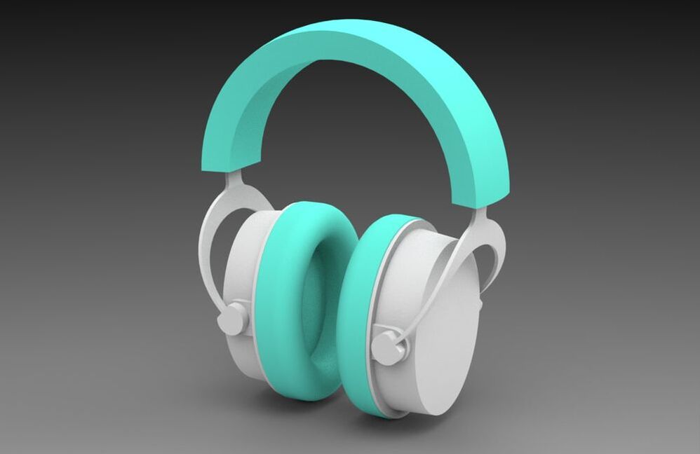
First, you will need dimensions: you can get them from a detailed technical drawing or measure a real-life object yourself. Then you’ll go through the process of modelling it. During this process, you’ll manage obstacles, learn from mistakes, make adjustments, and persevere until you’re satisfied with your project. When you complete your final work of wonder, it will boost your self-confidence because it’ll be something that you’ve created on your own.
We have discussed how project-based learning will help you in learning SOLIDWORKS, but let’s see how it works. Below is a video that touches on project-based learning and goes over a simple project from scratch. Check it out to build your first simple project.
We have discussed how project-based learning will help you in learning SOLIDWORKS, but let’s see how it works. Below is a video that touches on project-based learning and goes over a simple project from scratch. Check it out to build your first simple project.
We also have a fully structured program based on several meaningful real-world objects that will push you to your limits and hone your SOLIDWORKS skills. Do check it out if you want to grow your 3D modeling skills with real-life projects. Hope to see you there!

by Mohsina Zafar
Mohsina is a Mechatronics engineer who is passionate about 3D design and artificial intelligence. She specializes in SOLIDWORKS 3D CAD and loves to help students solve their SOLIDWORKS problems.
LinkedIn: https://www.linkedin.com/in/mohsina-zafar/
LinkedIn: https://www.linkedin.com/in/mohsina-zafar/
Innovation is a word that gets thrown around a lot, but it’s not always clear what innovation means. It can be used to refer to anything from introducing new products or services to creating a better way of doing something. It can also refer to the process of developing new ideas and turning them into reality. The goal of innovation is always improvement—either for the user or for the company as a whole. If you want your business to stand out in today's competitive marketplace, you need to think creatively about how you can improve your products and services so they meet customer needs better than other companies do theirs.
What is Innovation?
Innovation is the process of introducing new ideas, products, and services. It can come from anywhere, and it can be big or small. Innovation requires an open mind and a willingness to take risks—you never know what might be on the other side!
Oftentimes, innovation is linked to commercialization with something new. A simple way to understand this is with the equation: Innovation = Invention + Commercialization/Implementation. Another term you might have come across is Design Innovation. For this article, we'll treat them the same way to keep things simple. You can check out our What is Design Innovation article to know more.
Oftentimes, innovation is linked to commercialization with something new. A simple way to understand this is with the equation: Innovation = Invention + Commercialization/Implementation. Another term you might have come across is Design Innovation. For this article, we'll treat them the same way to keep things simple. You can check out our What is Design Innovation article to know more.
Innovation is an important tool for driving growth.
Innovation is an important tool for driving growth. Innovation is a key driver of economic growth, as new ideas and products can lead to increased productivity and efficiency. Therefore, organizations must innovate in order to survive in today’s business environment.
Innovation is an organizational process that leads to the development of new ideas or initiatives (e.g., products or services) that meet customer needs better than existing offerings do. The end result can be either incremental improvement on an existing product or service. It can also result in radical changes that create new markets and industries altogether. Even though we love hearing about disruptive innovations, most innovations out there are incremental.
Innovation is an organizational process that leads to the development of new ideas or initiatives (e.g., products or services) that meet customer needs better than existing offerings do. The end result can be either incremental improvement on an existing product or service. It can also result in radical changes that create new markets and industries altogether. Even though we love hearing about disruptive innovations, most innovations out there are incremental.

Innovation is about more than just invention.
Innovation is about more than just invention. Innovation is a system that must be cultivated and fostered, with corporate support and buy-in across the entire enterprise. This includes a willingness to invest in research and development (R&D) activities to promote creativity in both individual employees and teams, as well as to take risks when necessary. Innovation also includes the commercialization of inventions—the process by which an idea becomes a product or service useful for society at large.
Many different frameworks, tools, and approaches can help in generating relevant innovation. You can explore some of them on our Design Innovation Frameworks and Tools page.
Many different frameworks, tools, and approaches can help in generating relevant innovation. You can explore some of them on our Design Innovation Frameworks and Tools page.
Innovation can be a business's most valuable asset.
Innovation is a business’s most valuable asset. It is the main ingredient for success in an increasingly competitive global economy and can be considered a long-term strategy for sustainable growth. It is a critical component of your company’s strategy because it allows you to differentiate yourself from other companies, gain a competitive advantage, and create new opportunities for growth.
Innovation is a system that must be cultivated and fostered.
Innovation is a system that must be cultivated and fostered, with corporate support and buy-in across the entire enterprise. It’s not a project, it’s not just an event—it’s a culture.
Innovation is a mindset, not a project; it's an approach to problem-solving rather than just another solution to the same old problems. Innovation isn't something you do once or twice; it's part of your way of life at work every day (and night).
Innovation is a mindset, not a project; it's an approach to problem-solving rather than just another solution to the same old problems. Innovation isn't something you do once or twice; it's part of your way of life at work every day (and night).
Innovate or die.
You might have heard the phrase 'innovate or die' before. Does that hold true? Innovation is critical to a company’s survival in today’s business environment. The pace of change is accelerating, and customers have more choices than ever before. If you don’t innovate, you will be overtaken by others who do. Innovation isn't just about products or services—it's about how we work together, what we learn from our customers and each other, the way we collaborate on innovation projects across the organization, how we share our knowledge with the world, even how we use data analytics to improve our processes and productivity.
A great example of innovation at work in today’s economy comes from Airbnb's approach to customer service: Rather than having customer service representatives answer generic questions over email or chatbots respond with canned responses whenever someone has an issue with their site technology (which happens frequently), Airbnb hires people who are experts at solving specific problems for each type of traveler so they can resolve issues quickly without requiring the assistance of someone else.
Innovation is key to survival in today’s business environment. Innovation is the engine of growth, and it's a necessity for survival in today’s competitive landscape. Innovation is a must-have for any company hoping to stay relevant in the modern economy.

Why is innovation important?
Innovation is the key to success, and it helps us solve problems, be more creative, and be more efficient.
When it comes to innovation, there are many different approaches that you can take, but one thing is clear: the most successful innovative companies have a purpose beyond making money. They have a passion for what they do, they care about their customers, and they believe in themselves and their team members. Innovation is about solving real problems for real people with real needs—and being proud of your achievements, as well as being willing to learn from mistakes along the way. Innovation is not about making things pretty or building the biggest company in your industry, it’s about making them effective and relevant to your shareholders.
Innovation is important because it allows us to solve any kind of problem, face any kind of challenge, and address any kind of issue in the future. In today's world where we have so many problems and challenges, innovation is extremely important. Innovation can be small or large; it can be transformative or incremental—but it will always have an impact on society and the way we live our lives. This is especially the case as we are facing a very uncertain future.
Conclusion
Innovation is one of the most powerful tools in business today. It can help you differentiate yourself from competitors, build a competitive advantage, and drive growth. It’s also important to remember that innovation isn’t just about inventing something new—it involves everything from refining processes to changing how we think about customers and their needs. In short, innovation is an essential part of any company’s success. If you would like to have a conversation about design innovation and its different processes, make sure to drop us a line. You can also sign up for our mailing list to get the latest innovation insights. Just write your name and email on the little form you will find on the upper right part of this page.
By Tayseer Almattar
Tayseer is a passionate designer and educator. He believes that innovation potential can be grown and neutered within organizations with relevant design innovation processes.
LinkedIn: https://www.linkedin.com/in/tayseer-almattar-design-innovation
Tayseer is a passionate designer and educator. He believes that innovation potential can be grown and neutered within organizations with relevant design innovation processes.
LinkedIn: https://www.linkedin.com/in/tayseer-almattar-design-innovation
Imagine you need to create two objects with slight differences. One way is to create each of them from scratch. But this will be time-consuming and tedious as only a few adjustments to one object can result in the other one. This will also result in multiple files, which will get harder to manage as the number of objects increases. In a previous post, we addressed how you can create design configurations using Excel Design Table to address this situation.
Here, we will talk about how SOLIDWORKS configurations can rescue with a more direct way to create configurations. SOLIDWORKS allows you to create multiple variations of a model. Different configurations can be created by changing dimensions, suppressing features, etc. As these configurations are in a single file, organizing them also becomes easy.
In this article, we will explore how you can speed up your 3D modeling by creating multiple variations of your design by creating configurations manually.
In this article, we will explore how you can speed up your 3D modeling by creating multiple variations of your design by creating configurations manually.
How to Create Configurations?
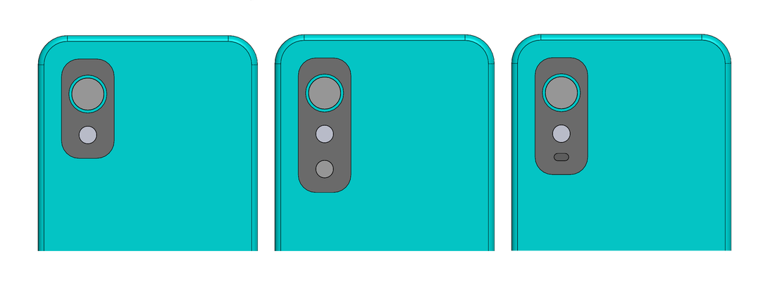
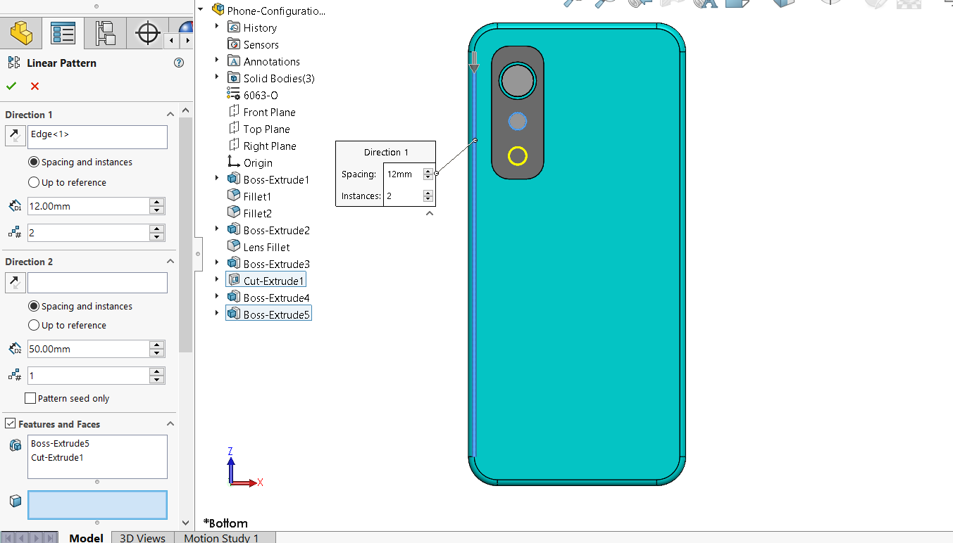
Imagine that you designed a phone for a client. Now they want to know how adding camera lenses and flashlights will affect the aesthetics. You are expected to share a few variations by playing around with shapes. This is where you utilize your knowledge of configurations. Following is the phone model:

Go to ConfigurationManager > right-click on part/assembly name > select “Add Configuration”. In propertymanager, you can specify the name and description of the new configuration.
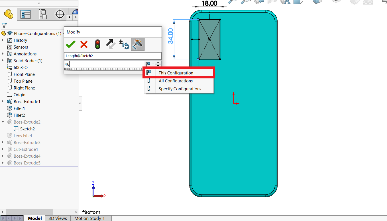
When it’s created, go to the FeatureManager Design Tree to change dimensions and/or suppress or unsuppress features. While changing the dimension, you can specify if you want the change to be reflected in the current configuration, specific configurations, or all configurations.
You can add and suppress multiple features in each configuration. In the image below, another secondary camera is added by using the linear pattern.
You can go back to your ConfigurationManager, add, and adjust another configuration. In the image below, the secondary camera previously added is suppressed, and a straight slot is added to represent the flashlight in a new configuration.
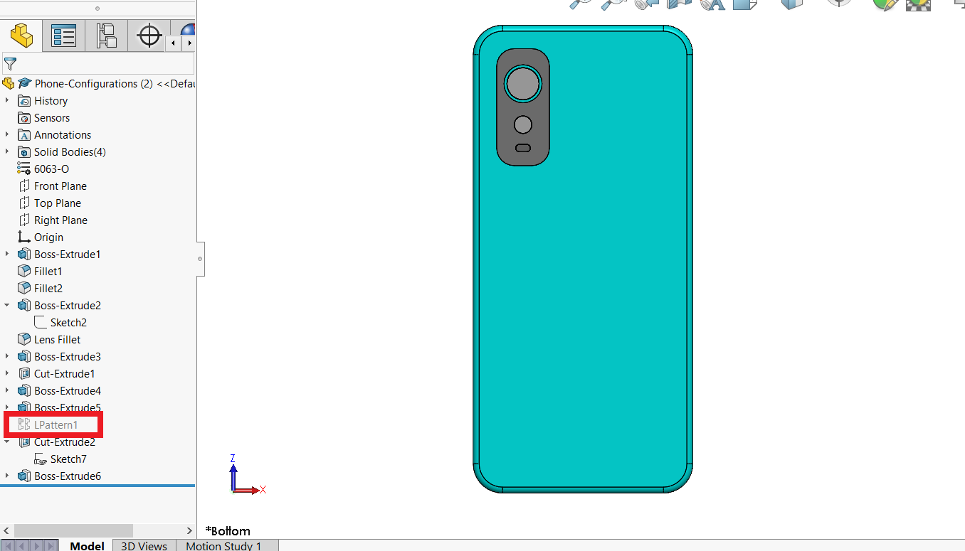
Before you conclude your design, it’s a good practice to double-check if all your configurations are as you expect them to be. Go to the ConfigurationManager to view the list of added configurations. Double-click on the configuration that you want to activate, and that’s it! You have successfully created multiple versions of the model by manually creating configurations.
Using this knowledge, you can easily create a family of similar objects without the hassle of creating them individually. Will you be using configurations to ease your design process? Let us know in the comment section.
If you want to learn more advanced topics like this, check out the professional-level SOLIDWORKS program at the TforDesign School. You will get access to top-notch content and experts supporting your learning journey.
If you want to learn more advanced topics like this, check out the professional-level SOLIDWORKS program at the TforDesign School. You will get access to top-notch content and experts supporting your learning journey.
by Mohsina Zafar
Mohsina is a Mechatronics engineer who is passionate about 3D design and artificial intelligence. She specializes in SOLIDWORKS 3D CAD and loves to help students solve their SOLIDWORKS problems.
LinkedIn: https://www.linkedin.com/in/mohsina-zafar/
LinkedIn: https://www.linkedin.com/in/mohsina-zafar/
Let's start with an intro
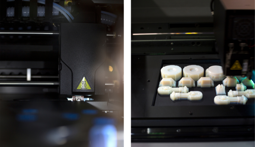
3D printing is the process of creating a three-dimensional object from a digital file. It works by melting or solidifying plastic or other materials and laying down successive layers to create an object.
3D printing has become one of the most popular technologies in product design today, with more and more designers using it for everything from concept models to final prototype production. This article explores how 3D printing can work for your design workflow and some of the challenges you might face along the way.
3D printing has become one of the most popular technologies in product design today, with more and more designers using it for everything from concept models to final prototype production. This article explores how 3D printing can work for your design workflow and some of the challenges you might face along the way.
What is 3D printing?
3D printing is a process of making three-dimensional solid objects from a digital file. 3D printing or additive manufacturing (AM) technology has been around since the 1980s. Since then, the 3D printing market size has been growing while adding lots of value to many businesses. However, it only recently became affordable for home and business use.
3D printing is also known as Additive Manufacturing (AM) or Rapid Prototyping. An AM machine can print an object by building it up in layers based on the design you created in your CAD program, often using plastic materials that are melted and then cooled to create the final product. The 3D printer builds up each layer by adding material until the object is complete.
3D printing is also known as Additive Manufacturing (AM) or Rapid Prototyping. An AM machine can print an object by building it up in layers based on the design you created in your CAD program, often using plastic materials that are melted and then cooled to create the final product. The 3D printer builds up each layer by adding material until the object is complete.

Product design workflow with 3D printing
3D printing is a tool, not a solution. It’s important to remember that 3D printing is just one component of product design, and it will never be able to solve every problem in your workflow. 3D printing can help you:
- Create more innovative products with less risk
- Reduce time-to-market by reducing complexity during prototyping
- Optimize the manufacturing process by testing multiple prototypes at once
Benefits of 3D printing in product design
3D printing offers a number of benefits in product design.
- Reduce time to market: With traditional manufacturing, it can take weeks or months to get a prototype ready for testing, but with 3D printing, you can have an accurate prototype in just hours. This is especially beneficial when working with low-volume production runs that may not justify the cost associated with traditional manufacturing methods.
- Reduce the cost of development: 3D printing makes it possible for manufacturers to iterate on their designs quickly and efficiently because they don't have to wait for new tooling or molds before testing changes made to the design. This means less money spent on prototyping costs and faster turnaround times from concept through final product release (which translates into increased revenue).
- Increase quality of design: With traditional manufacturing methods, you often have very little control over the final product's appearance because parts must be molded or cast one at a time. With 3D printing technology, however - which enables designers to create finished prototypes that look exactly like the final version - there's greater flexibility in producing mirror scale models as well as functional prototypes that are more representative than what would normally be available through other fabrication processes such as casting/molding or machining.
Challenges of 3D printing in product design
Despite the hype, 3D printing is not a cure-all for all design problems. In fact, it is often not an appropriate solution for even the most fundamental aspects of product design.
- 3D printing is not suitable for all materials: Because it creates parts by fusing material together in layers, 3D printing is unsuitable for producing parts made of materials that melt or burn at low temperatures (like foam and rubber).
- Access to the technology might not be as prevalent: some consumer-level 3D printing technologies like FDM and SLA are becoming more available nowadays. However, the majority of 3D printing technologies are still relatively hard to access due to their high cost and lack of expertise to operate them.
Role of 3D printing in the product development process
3D printing is an important technology in the product development process. Because of its speed, accuracy, and affordability, 3D printing is used at any stage of the design process. Design teams use 3D printing to validate ideas and concepts early on in the design process. This saves time and money by helping designers avoid costly rework later on in the development cycle.
The first stage where 3D printing can be applied is during initial prototyping. Prototypes are often printed as fast as possible so that they can be evaluated by users or other stakeholders as soon as possible. These prototypes are typically not intended for mass production but rather serve as a proof of concept or idea validation tool that helps designers decide if their current direction is heading towards something worth pursuing further. The benefit of using 3D printing technologies is that they allow you to produce multiple iterations quickly without having to wait for molds or tooling, which often takes months before being produced in metal or plastic components!
The first stage where 3D printing can be applied is during initial prototyping. Prototypes are often printed as fast as possible so that they can be evaluated by users or other stakeholders as soon as possible. These prototypes are typically not intended for mass production but rather serve as a proof of concept or idea validation tool that helps designers decide if their current direction is heading towards something worth pursuing further. The benefit of using 3D printing technologies is that they allow you to produce multiple iterations quickly without having to wait for molds or tooling, which often takes months before being produced in metal or plastic components!
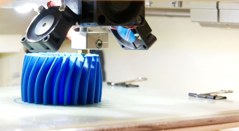
Product designers are using more and more advanced technologies to develop innovative products for the global market.
3D printing is a fast and efficient process. Designers can create, prototype, and test their products in as little as a day. This technology has been used to produce everything from intricate medical devices to custom-made shoes for astronauts on the International Space Station.
Product designers often use 3D printing to create prototypes of new products or make small changes to existing ones. Prototypes help them test the functionality of their designs before they go into full production, which saves time and money because there is no need for large-scale manufacturing until the design is finalized.
3D printing also allows companies to design unique items that aren't available through traditional manufacturing methods, such as injection molding or casting (the process by which metal or plastic parts are created by pouring liquid material into a mold).
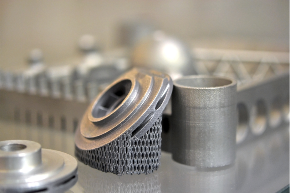
Let's wrap up!
3D printing is becoming more and more popular as a tool for product design. In this article, we discussed the benefits of using 3D printing in product design and outlined some of the challenges that designers face when using this technology for their projects. We also talked about how 3D printing can help designers create prototypes faster than ever before!
Now that you have an idea of the great value 3D printing can bring you, you should consider diving deeper into exploring what the technology is all about and exploring all the values it can bring you. Luckily, we have a comprehensive program made just for that: 3D Printing Opportunities and Applications. Make sure to check it out, we are looking forward to seeing you there.
Now that you have an idea of the great value 3D printing can bring you, you should consider diving deeper into exploring what the technology is all about and exploring all the values it can bring you. Luckily, we have a comprehensive program made just for that: 3D Printing Opportunities and Applications. Make sure to check it out, we are looking forward to seeing you there.
Over the last few months, we have been working on launching Asteria, a new brand in the tea lifestyle space. We put together a small team and started working on designing and building both a brand and our first product, Explorer 1.0.
When building the brand, we played with colors, built prototypes, and dealt with manufacturing. We had fun, got into stressful times, and learned a lot. Here are three little random lessons we’ll keep in mind.
When building the brand, we played with colors, built prototypes, and dealt with manufacturing. We had fun, got into stressful times, and learned a lot. Here are three little random lessons we’ll keep in mind.
1- Prototype, Talk to People, but Don’t Expect them to Do Your Job
First, let us clarify that virtual prototypes of pictures and 3D models are great. However, they are by no means a replacement for physical prototypes. Strive to end up with physical prototypes and have other people outside your team interact with them. Then, observe, and get feedback from those people. This is all obvious, right? Here are the little things to watch out for:
- Don’t send a survey. Meet your subjects in person for an intimate conversation whenever possible.
- Plan your interview, then Ask open-ended follow-up questions on every point: ‘Why’ and ‘How’ are your best friends.

During those interactions, know their duty and your job. Their duty is to provide personal insights from their perspectives and situations. They are not there to suggest solutions to the problems you are trying to solve, that’s your job.
2- Colors and Coloring Standards
This one might be a little obvious to some, a little hidden to others. When building a brand that might end with physical products, you’ll need to pick your coloring system carefully, especially if you are keen on keeping consistent branding. There are multiple coloring systems out there. Let’s go over some major ones:
- HEX: Perfect for web applications with a nearly unlimited collection of colors.
- RBG: Another good option for screens and digital applications
- CMYK: Work better for physical objects
- Pantone: A proprietary system that works well with printing and paint

CMYK and Pantone have less variety of colors but are more viable for the physical world. So, a good approach is to start there. You will most likely be able to find identical colors in HEX and RBG after. Also, pick your brand colors out of official colors prints, not screens.
The colors might already look slightly different when dealing with different printers/ printing service providers. Those differences might be because of the product’s materials or the different machines/techniques used to do the coloring. However, you don’t want to be subjected to more variance because one manufacturer has less flexibility than another due to your coloring codes. Suppose you use the HEX system to choose your brand colors. In that case, there is a higher likelihood that you will not be able to replicate the exact color of physical objects.
The colors might already look slightly different when dealing with different printers/ printing service providers. Those differences might be because of the product’s materials or the different machines/techniques used to do the coloring. However, you don’t want to be subjected to more variance because one manufacturer has less flexibility than another due to your coloring codes. Suppose you use the HEX system to choose your brand colors. In that case, there is a higher likelihood that you will not be able to replicate the exact color of physical objects.
3- Work with Your Manufacturers
Knowing how things are made from a manufacturing perspective is a good idea. However, even with that knowledge, always ask for your manufacturer’s opinions. Your success of the manufacturer’s best interest as this means you will be more likely to return for more of their service. This is not to mention that they have a reputation to protect.
Many people overestimate the knowledge they need to have to communicate with manufacturers. In reality, most manufacturers don’t expect you to be an expert in their fields, which is why they often have engineers to help you manufacture your design. This includes suggesting ways to make your design more manufacturable.
Many people overestimate the knowledge they need to have to communicate with manufacturers. In reality, most manufacturers don’t expect you to be an expert in their fields, which is why they often have engineers to help you manufacture your design. This includes suggesting ways to make your design more manufacturable.
Different manufacturers are often specialized in one or two things. For example, a box manufacturer will likely be able to work from the box sketches you have on a napkin because that’s all they do. A prototyping facility that does 3D printing would tell you the parts of your design that are not possible to make and likely provide some recommendations to tackle those issues. Again, it is helpful if you know how manufacturing works so you can save tons of valuable design time, but keep in mind that manufacturers are often there to help.
Also, always contact more than one manufacturer, check on different qualities and compare the different customer support, qualities, and prices you can get. If you have the time and money, get a manufacturing prototype for your final designs well.
Here you have it, those are three random little lessons we got to learn more of in our journey to build Asteria. Would you like us to share more practical lessons? Let me know in the comment below. Also, don’t forget to share your experiences and things to watch out for when designing a new product. If you would like us to share the whole Asteria building experience, let us know in the comments.
Finally, if you are looking for help to build your own brand, drop us a line. We are here to help.
By Tayseer Almattar
Tayseer is a passionate designer and educator. He believes that innovation potential can be grown and natured within organizations with relevant design innovation processes.
LinkedIn: https://www.linkedin.com/in/tayseer-almattar-design-innovation
LinkedIn: https://www.linkedin.com/in/tayseer-almattar-design-innovation
Imagine you need to create two or more objects with slight differences. One way is to create each of them from scratch. But this will be time-consuming and tedious as only a few adjustments to one object can result in the other one. This will also result in multiple files, which will get harder to manage as the number of objects increases.
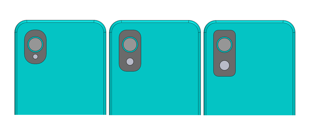
This is where SOLIDWORKS configurations come to the rescue. SOLIDWORKS allows you to create multiple variations of a model. Different configurations can be created by changing dimensions, suppressing features, etc. As these configurations are in a single file, organizing them also becomes easy.
In this article, we will explore how you can speed up your 3D modeling by creating multiple variations of your design using a Microsoft Excel design table.
In this article, we will explore how you can speed up your 3D modeling by creating multiple variations of your design using a Microsoft Excel design table.
What is an Excel Design Table?
A Design Table is an Excel spreadsheet that is embedded in the SolidWorks environment. Entries of this table control model variations.
Imagine that you designed a phone for a client. Now they want to know which position of camera lenses will work best for design and functionality. You are expected to share a few variations. This is where you utilize your knowledge of design tables. Following is the phone model:
Imagine that you designed a phone for a client. Now they want to know which position of camera lenses will work best for design and functionality. You are expected to share a few variations. This is where you utilize your knowledge of design tables. Following is the phone model:
For convenience, start by renaming the dimensions and features based on what they represent. This makes it easier for you to refer to them while working on the design table. Double-click on the dimensions and features to rename them.
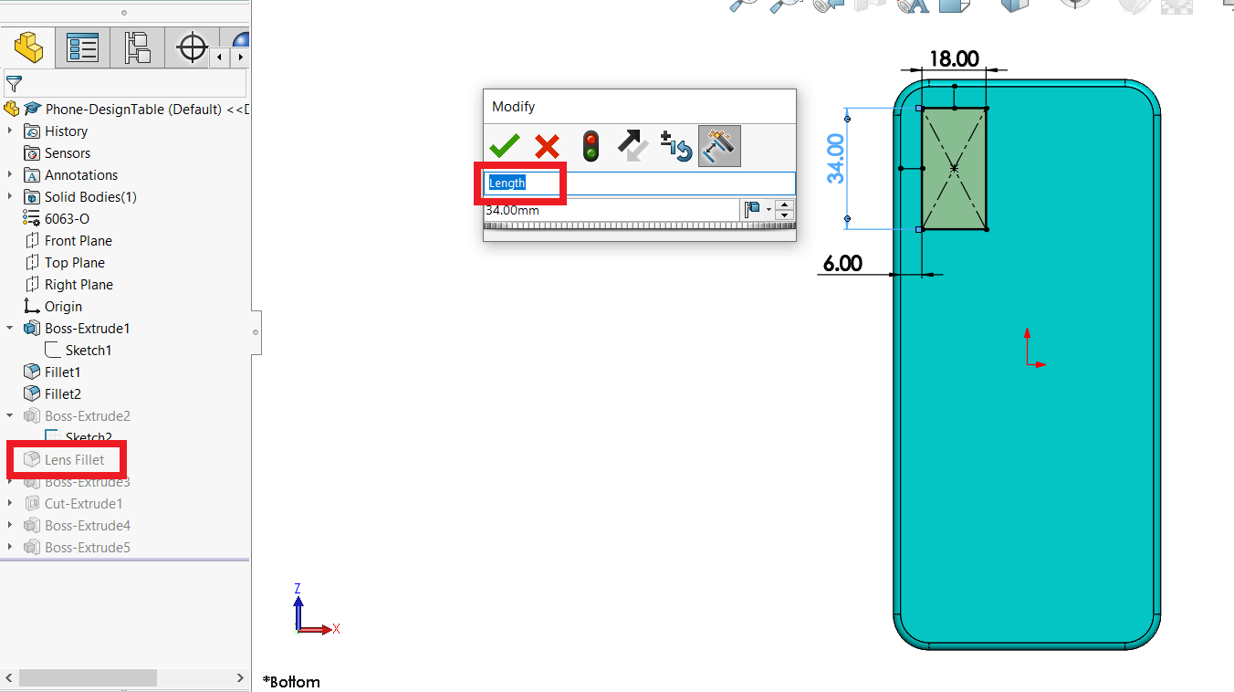
How to Create a Design Table?
To create and access Design Tables, you need to have MS Excel installed on your system. To create a Design Table, go to Insert > Tables > Excel Design Table. In the Design Table PropertyManager, you have the following options:
- blank design table
- get it from an Excel file
- have SOLIDWORKS auto-create it
Use this design table to define different configurations. You can start changing dimension values/suppression states as per your design requirements. Once you’re done, click outside the table, and you will get a pop-up showing the newly created configurations. Go to the ConfigurationManager to view the list of added configurations. By default, any part modeled in SOLIDWORKS is set as the default configuration.
Double-click on the configuration that you want to activate, and that’s it! You have successfully created multiple versions of the default model using an Excel design table.
Now using this knowledge, you can easily create families of similar objects without going through the hassle of creating them individually. Will you be using Design Tables to ease your design process? Let us know in the comment section.
If you want to learn more advanced topics like this, check out the professional-level SOLIDWORKS program at the TforDesign School. You will get access to top-notch content and experts supporting your learning journey.
If you want to learn more advanced topics like this, check out the professional-level SOLIDWORKS program at the TforDesign School. You will get access to top-notch content and experts supporting your learning journey.
By Mohsina Zafar
Mohsina is a Mechatronics engineer who is passionate about 3D design and artificial intelligence. She specializes in SOLIDWORKS 3D CAD and loves to help students solve their SOLIDWORKS problems.
LinkedIn: https://www.linkedin.com/in/mohsina-zafar/
LinkedIn: https://www.linkedin.com/in/mohsina-zafar/
If you are ever thinking about designing or building any product, you’ll have to build a prototype. So, what are the different types of prototypes for physical products? Let us talk about this here.
In a broad sense, a prototype is whatever can make your idea more tangible. A prototype can make your idea feel more real, which can help you gather more support to bring it to life. Prototypes can help you develop, test, and improve your products. Possibilities are that you CANNOT develop a good product without Prototyping.
In a broad sense, a prototype is whatever can make your idea more tangible. A prototype can make your idea feel more real, which can help you gather more support to bring it to life. Prototypes can help you develop, test, and improve your products. Possibilities are that you CANNOT develop a good product without Prototyping.
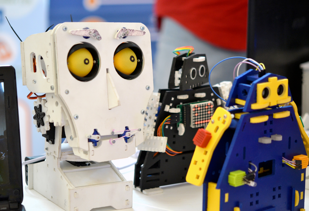
There are three major types of prototypes out there. Each type serves a different purpose. So, let us explore those first. Then talk about how to look at them practically.
The three types are Aesthetic prototypes, Functional prototypes, and Manufacturing prototypes. You might hear people refer to them with different names, which is okay. In this article, we will focus on the idea behind each type.
The three types are Aesthetic prototypes, Functional prototypes, and Manufacturing prototypes. You might hear people refer to them with different names, which is okay. In this article, we will focus on the idea behind each type.
- An aesthetic prototype aims to show your design's appearance or expected appearance. It often has no function at all. Its purpose is to show the appearance of the design or test its ergonomics. For example, the aesthetic prototype of a smartphone might only be a shell of its external shape.
- A functional prototype aims to show the function of the product. Its purpose is to prove that the technology you are developing is feasible. For example, the functional prototype of a smartphone can be all the electronics connected on a big breadboard.
- A manufacturing prototype aims to replicate the final product that will end up being commercialized. Its purpose is to ensure that both esthetic and function can merge together and also test the product further before investing in manufacturing. For example, a manufacturing prototype of a smartphone can be a full-functioning smartphone that looks just like the one you can buy from the shop.
A prototype is whatever can make your idea more tangible. A prototype can make your idea feel more real, which can help you gather more support to bring it to life.
Those are the classical types of physical prototypes. On paper, we often think about them as aesthetic, functional, or manufacturing prototypes. In practice, your prototypes might be somewhere in between. So, it might be better to consider those categories as a spectrum rather than fixed types. Your prototypes can then fall somewhere in between. You will most likely move closer to the manufacturing prototype as you progress in your product development process.
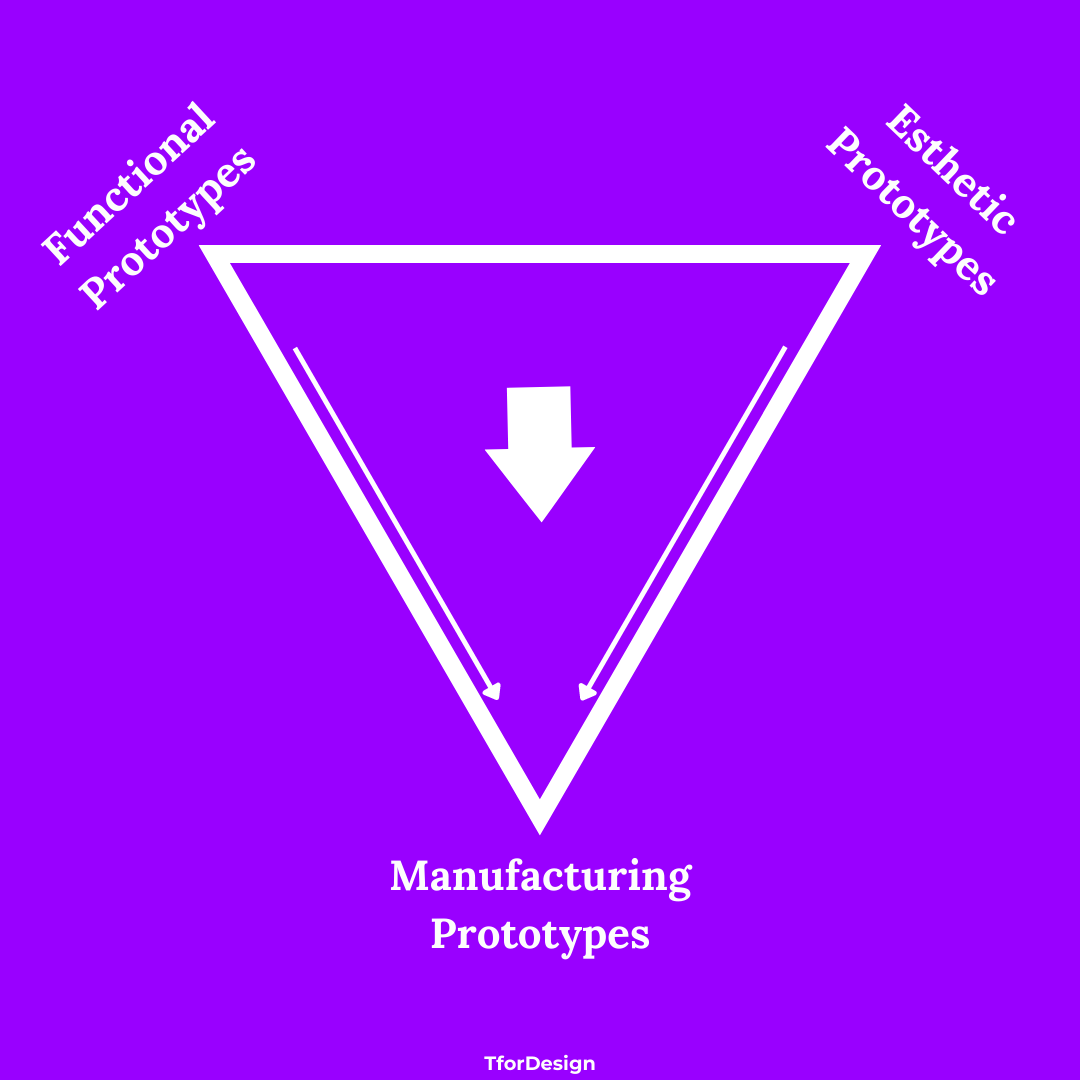
Keeping those different types and purposes in mind when planning your prototypes is essential. This will help you build more precise plans for your prototypes and make the prototyping conversation easier with your teammates and other stakeholders.
So, here you have it, those were the different types of physical prototypes you would most likely engage with. Even though the above classification might be more relevant to physical prototypes, prototyping practices have expanded with the rise of the service economy and digital products. Would you like another article just on those expansions? Let us know in the comments below. You can also check out our Intro to Prototyping Program to know more about the practice of Prototyping.
Back to you now, what are your thoughts on Prototyping, and what are your experiences with it? Were you familiar with the types of prototypes we mentioned here? We would love to hear your thoughts in the comments below.
By Tayseer Almattar
Tayseer is a passionate designer and educator. He believes that innovation potential can be grown and nurtured within organizations with relevant design innovation processes.
LinkedIn: https://www.linkedin.com/in/tayseer-almattar-design-innovation
LinkedIn: https://www.linkedin.com/in/tayseer-almattar-design-innovation
Coming up with 'ideas' is sometimes a difficult task as it can be too abstract and lack structure. To make this easier, let us look at eight different ways or methods you can use to generate innovations with market potential quickly.
1. Find an alternative method to accomplish what an existing innovation accomplishes: The fact that a company or a firm started to produce a product that addresses a NEED can indicate that fulfilling that NEED is a viable opportunity. This is as if the other company has identified the location of a hidden treasure for you. Coming up with other innovations that would satisfy that NEED can yield a great opportunity.
1. Find an alternative method to accomplish what an existing innovation accomplishes: The fact that a company or a firm started to produce a product that addresses a NEED can indicate that fulfilling that NEED is a viable opportunity. This is as if the other company has identified the location of a hidden treasure for you. Coming up with other innovations that would satisfy that NEED can yield a great opportunity.

2. Follow what you like: list your passions and observe how technologies evolve around you. Then look for innovative opportunities that would keep you excited and happy. There is a good possibility if this passion got you super excited, there are many out there who can be excited about the same thing.
3. Tackle what annoys you: take another look at your daily life and see what annoys you. Do you get annoyed because of how the flour is being packaged? Do the methods available to find home service providers annoy you? How about you spend time resolving those issues and make your life easier? There is a good possibility that you can also make other people’s lives easier as well.
4. Provide a better-quality commodity (and make it more expensive): In other words, make an existing product or service more premium. Go to the market and find all the inexpensive commodities. Those have been commodities for long enough that you will find it difficult to distinguish the different brands as they all look similar with about the same price. Then, consider providing a deluxe version. Many customers might be willing to pay extra for better packaging or better quality.
5. Make it cheaper: what are products or services that are considered to be premium? Can you provide a similar service or product at a considerably lower price? For example, have you noticed that a premium wireless keyboard costs at least a hundred dollars? Can you make it for fifty? This does not have to be in tech. Many players in the food and beverage industry adopt this approach, too. For example, you might notice that Sushi in your city or country is relatively expensive. Can you create an alternative experience that can be more affordable and still maintain good quality?

6. Move something from Industry-level to Consumer-level: have you noticed that some products are only available at an industrial level where only companies enjoy such products at a high cost? Can you make that product cheaper for home users or small companies with similar features? For example, 3D Printing has long been available for industries for about four decades. However, this luxury has become available to ordinary people in the last decade, giving rise to an industry worth more than half a billion US Dollars. In this, we are talking about consumer-level 3D printers.
7. Follow New Trends: what changes in technology, culture, and lifestyle happen around you? Are people in your community suddenly started to consider their personal health more? Can you use that trend to produce new products or provide new services? What new products can you provide given the trend of mobile technology? The Internet of Things? Blockchain? Web 3.0? NFTs? etc?
8. Manipulate existing attributes of a product: what attributes do marketers give to smartphones? Size, weight, battery life, screen display, processing power, etc. Now, which of those attributes can be eliminated, reduced, or raised above expectations? What new attributes can be introduced into the smartphone industry? Manipulating those attributes can quickly generate new products and services that serve a more specific or more general audience which can be an innovation of good market potential.

Here you go, those are eight simple methods to develop innovations with market potential quickly. Keep in mind they are best used as inspirations. You can use them to guide or spark new conversations within your organization, community, or network. So, they are not absolute methods. Carrying out any specific innovation would still require lots of work at many different levels.
Back to you, which of the methods resonates most with you? How do you usually think about bringing new ideas? Share your thoughts with us in the comments below. What innovations came to your mind after reading those eight methods?
If you are looking to engage with a community of design innovators, join our online Facebook Design Innovation Community.
By Tayseer Almattar
Tayseer is a passionate designer and educator. He believes that innovation potential can be grown and natured within organizations with relevant design innovation processes.
LinkedIn: https://www.linkedin.com/in/tayseer-almattar-design-innovation
LinkedIn: https://www.linkedin.com/in/tayseer-almattar-design-innovation
If you are here, you must know about 3D modeling. You could have also had some thoughts about learning how to build 3D models. However, why would you want to learn 3D modeling? Let us talk about this here. I will share my point of view first. Then I would like to hear it from you in the comments where we can have a small discussion.
Meet Gallon
First, let me introduce you to Gallon, which you can see in the image below. Gallon was a character we conceived a while ago. If you follow TforDesign, you will surely come across Gallon.
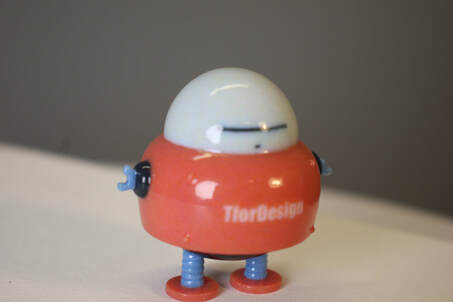
In this blog, we will not talk about how we conceived Gallon. Instead, we will focus more on what happened after we did. After the Gallon character was designed, we made a 3D model of it. Then, we emailed the 3D model to a manufacturing facility. After a few days, we got a box back. Inside that box were little tangible Gallons that we could touch and feel.
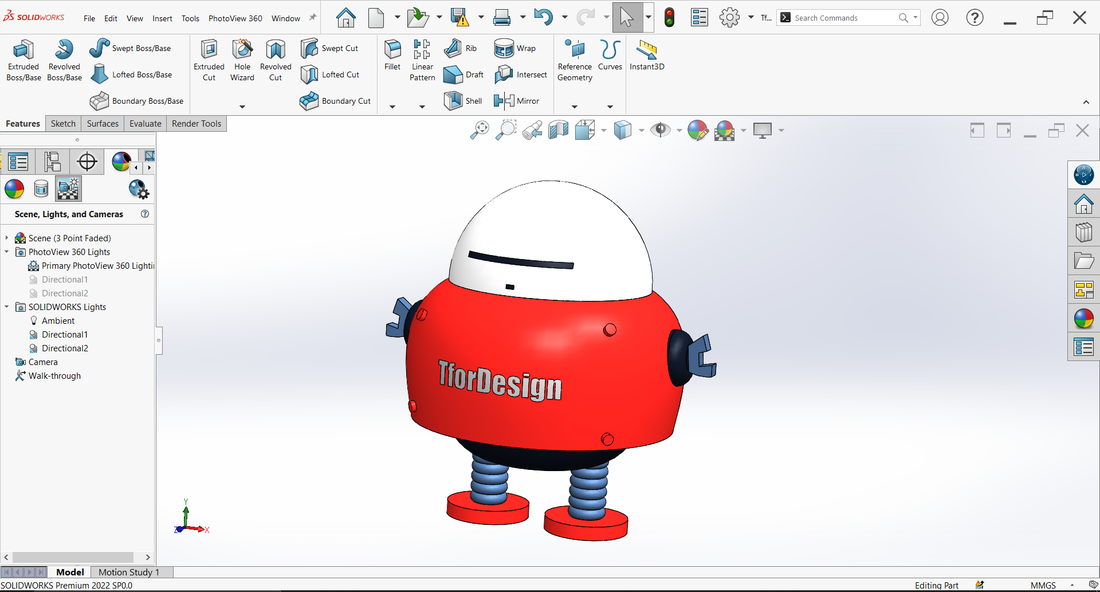
Modern Manufacturing and the Making of Gallon
To make Gallon, we went on a journey of making. Key elements of this journey were defining the requirements, building and verifying 3D models, then manufacturing. 3D modeling was right at the center of this journey. 3D modeling is growing to be both a virtual prototyping tool and a tool that enables us to make tangible objects. The final manufacturing can happen through different means like a 3D printer you have a home, a machine shop, or through outsourcing like we did in the case of Gallon.
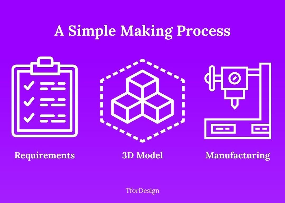
3D modeling is strongly related to manufacturing as manufacturing is becoming more digitalized, with manufacturing machines getting their input by interpreting 3D models. Examples of growing digitalized machines include 3D printers and CNC machines. This makes 3D modeling more essential to modern manufacturing. Thus, we can think of 3D modeling as a superpower. That super is the freedom to make tangible objects. Suppose you have that superpower, congratulations. If not, you can start learning it today.
If you are an organization or an individual, you can think of 3D modeling as being all about this superpower. It enables the organization to visualize its products, prototype them, and communicate them with manufacturing. This is one big reason why we advocate 3D modeling.
If you are an organization or an individual, you can think of 3D modeling as being all about this superpower. It enables the organization to visualize its products, prototype them, and communicate them with manufacturing. This is one big reason why we advocate 3D modeling.
How about you? Are you into 3D modeling? What made you start learning the skill? Make sure to let us know in the comments.
If you are considering learning 3D modeling, you can start with our Intro to 3D Modeling Program, which will build a strong foundation on what 3D modeling is all about. Suppose you want to start directly with learning a 3D modeling software. In that case, you can check out the different online SOLIDWORKS 3D modeling programs we have in the TforDesign School.
By Tayseer Almattar
Tayseer is a passionate designer and educator. He believes that innovation potential can be grown and natured within organizations with relevant design innovation processes.
LinkedIn: https://www.linkedin.com/in/tayseer-almattar-design-innovation
LinkedIn: https://www.linkedin.com/in/tayseer-almattar-design-innovation
A few years ago, I was in a classroom around the topic of managing value creation. As part of that, the questions of stakeholders and how to define them were central to the discussion. As an exercise, the leading professor gave us the hypothetical exercise of building a new monument on campus which we had to identify the stakeholders.
Attendants started shouting out different stakeholders, including the students, faculty, funders, visitors, construction workers, engineers, the designing architect, etc. The professor was still looking for one more particular stakeholder she had in mind. I raised my hand and said: “the birds.”
My classmates laughed as if I was telling a joke. That was not the sought-after answer, nor was it a rational answer in a room filled with corporate practitioners. The professor finally stated: “The fire department, is an important stakeholder that many tend to forget in the early design stages.” While I agree that the fire departments and other emergency services deserve a more central seat on the stakeholder’s table. I also wanted the birds to have an important seat as well. Unfortunately, that did not exist in the human-centered design thinking paradigm. This is even though the existence and thrival of the birds are tied to that of our own. However, what would happen if the birds had a central seat?

Can the birds be major stakeholders in design?
Where the Human-Centered Thinking Went Extreme
The concept of human-centered design brought about tremendous benefits to us in developing better products and services. However, does it mean human convenience is more important than that of other life forms?
When the industrial revolution kicked off, many of that period made a mistake assuming that natural resources are unlimited as well as nature’s ability to digest our trash. Arguably that revolution brought about false human independence from nature and formed a tiny seed of a human-centered world.
When the industrial revolution kicked off, many of that period made a mistake assuming that natural resources are unlimited as well as nature’s ability to digest our trash. Arguably that revolution brought about false human independence from nature and formed a tiny seed of a human-centered world.
Questioning the Human-Centered Paradigm
We have come a long way since the Industrial Revolution in realizing that natural resources are limited. We also came to understand that we share a finite planet with other life forms that have existed before us. More importantly, we realized that we could not exist on our own (even if, that might not be an enjoyable life). With this expansion of understanding, we might want to consider expanding our design thinking to match.
Adding Life to the Design Innovation Definition
We define design innovation as the bringing of innovations that are humanely desirable, technically feasible, and business-ly viable. For too long, we have defined good innovations on what is good for us, human-centered. However, that might have pushed us towards an egocentric obsession with our own well-being, neglecting the system that hosts us.
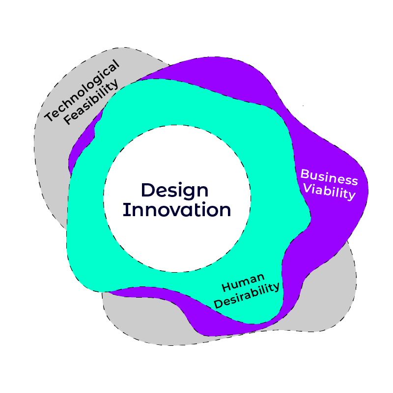
Our adapted Design Innovation model
Over the past decade, there has been a growing trend of organizations looking to minimize their negative environmental footprint. Minimizing is a good start, but the time will soon come when that is no longer enough. After all, minimizing damage is still damage, and putting forward the minimization question means that damage, in principle, is acceptable.
Back to our initial question: what would happen if the birds had a central seat at the stakeholder’s table? Minimizing damage will no longer be acceptable. Instead of asking how much damage you are causing, the more acceptable alternative would be asking how much life you are promoting.
Back to our initial question: what would happen if the birds had a central seat at the stakeholder’s table? Minimizing damage will no longer be acceptable. Instead of asking how much damage you are causing, the more acceptable alternative would be asking how much life you are promoting.
Re-thinking the Design Innovation Mode
With the points above, an alternative model for design innovation would have to answer the following questions:
P.s. We are building a community of people interested in design innovation and related topics using a Facebook group. Join us to connect and explore more on the topic.
- Is it viable from a business perspective?
- Is it desirable from a human perspective?
- Is it feasible from a technological perspective?
- Is it life-promoting from an environmental perspective?
P.s. We are building a community of people interested in design innovation and related topics using a Facebook group. Join us to connect and explore more on the topic.
By Tayseer Almattar
Tayseer is a passionate designer and educator. He believes that innovation potential can be grown and natured within organizations with relevant design innovation processes.
LinkedIn: https://www.linkedin.com/in/tayseer-almattar-design-innovation
LinkedIn: https://www.linkedin.com/in/tayseer-almattar-design-innovation
The term Design Thinking has become a global buzzword recently for all the right reasons. This is very different from the first time I gave a speech about the topic in 2013 when very few people heard the term.
I hope you have had a chance to experience it through a short workshop already. If not, let us know, and we can organize one for your team and/or organization. If you attended or facilitated one, then let's talk. Not about the workshop, but about what is next!
I hope you have had a chance to experience it through a short workshop already. If not, let us know, and we can organize one for your team and/or organization. If you attended or facilitated one, then let's talk. Not about the workshop, but about what is next!

What to take out of the workshop?
One day to learn something new is not much. You were probably introduced to a process and one or two tools that can aid that process. You moved a lot, used sticky notes, laughed, and hopefully had fun while at it.
After a fun day, you might go back to your office job and start thinking, what now? Suppose you are not in a leadership position. In that case, you might not have the authority to introduce new processes to the workplace. Was it all a waste? Hopefully, the answer is NO.
After a fun day, you might go back to your office job and start thinking, what now? Suppose you are not in a leadership position. In that case, you might not have the authority to introduce new processes to the workplace. Was it all a waste? Hopefully, the answer is NO.
Focus on the greater goal
The idea of Design as a method of problem-solving has a very central idea behind it. It is that we should keep the human at the center of our thinking. All the processes and tools used by design innovators lead to that. Luckily, as humans ourselves, we can relate to each other naturally without processes leading us.
So, if nothing else, drop the processes and the tools in your everyday work and start thinking about people as humans beyond the established status quo. If you can sneak in a tool or two, that is great. If not, the mindset of thinking about human needs is most important.
In a one-day workshop, this mindset of Design is all you need to get. It is simple and surely within your power to think of our fellow humans as such.
Think of chess or checker – It takes time
Whether you are looking at the design mindset or applying other design innovation processes, practice makes better (not perfect). You can think about design innovation like all other skills, the more you do it, the better you will get at it. Attending a one-day workshop is a great start. But, there is a huge world out there relating to Design Innovation. A one-day workshop is more like scratching the tip of an iceberg, again just all other fields.
If you are going beyond the design mindset to follow up with processes, don’t be a fundamentalist in following them verbatim. Often, that only repels people away from engaging with the process. Instead, always remember that the design mindset is more fundamental to the design processes.
If you are going beyond the design mindset to follow up with processes, don’t be a fundamentalist in following them verbatim. Often, that only repels people away from engaging with the process. Instead, always remember that the design mindset is more fundamental to the design processes.

How to infuse design innovation processes into your organization
Beyond the design mindset, design innovation methods, tools, and frameworks can greatly accelerate and enhance generating sustainable streams of innovations with higher success chances. The more serious an organization is about design innovation, the more it can include it in its operation. Integrating design innovation processes can be demanding. Thus, having an individual or a team responsible for guiding the innovation process adds considerable value. This could be an internal or external individual or team.
A good duty for that person is not to generate ideas but rather to guide the organization to innovate with its own mind power. S/he can get familiar enough with the organization to tailor innovation processes that would work for it. S/he can then walk the journey with everyone avoiding common issues that can take place like unintended biases or stagnation.
A good duty for that person is not to generate ideas but rather to guide the organization to innovate with its own mind power. S/he can get familiar enough with the organization to tailor innovation processes that would work for it. S/he can then walk the journey with everyone avoiding common issues that can take place like unintended biases or stagnation.
Let us summarize
Here are three main points you can take away from this:
- The design mindset about giving focus to human needs is at the center of design innovation.
- Design innovation processes and frameworks can greatly enhance innovation by building a structure to generate insights and translate them into tangible ideas.
- Infusing design innovation methods and frameworks can be demanding, and it's an area where a dedicated external or internal consultant can add significant value.
By Tayseer Almattar
Tayseer is a passionate designer and educator. He believes that innovation potential can be grown and natured within organizations with relevant design innovation processes.
LinkedIn: https://www.linkedin.com/in/tayseer-almattar-design-innovation
LinkedIn: https://www.linkedin.com/in/tayseer-almattar-design-innovation
The term innovation has become one of the buzziest terms in the last century. We can hear the word 'innovation' in every product announcement and find it listed on just about any organization's website. If we are outside stakeholders, this can be one more reason to admire that organization. However, employees can have a very different perception, a negative one. This is especially true when innovation is being applied to their work practices.
In one of my earlier work experiences, I recall my first-hand experience of the despise employees (my colleagues) had for innovation. To us, the popular management term meant confusion and extra work for no apparent reason. The term was overused to a level where no day will pass without sarcastic comments about anything called ‘innovation’.
In one of my earlier work experiences, I recall my first-hand experience of the despise employees (my colleagues) had for innovation. To us, the popular management term meant confusion and extra work for no apparent reason. The term was overused to a level where no day will pass without sarcastic comments about anything called ‘innovation’.

In an article published by Harvard Business Review, the author presents survey data on knowledge workers' drive to innovation varying between 14 to 28% in the US and Canada. Two economies are ranked 3rd and 16th respectively in the 2021 global innovation index. This is in contrast to a 2010 McKinsey global survey result showing that 84% of executives say ‘innovation is extremely important to their companies’.
The term 'innovation' is not bad in itself. In fact, it is easy to agree on how vital and central innovation is to both survive and thrive. However, applying and implementing innovations has been mishandled, giving it a negative connotation internally in many organizations. A big reason for that is that innovations are developed without the active participation of employees. Thus, it ends up being viewed as direct orders masked as innovations. This is especially the case when the new practice involves employees like new HR policies or new work practices.
The term 'innovation' is not bad in itself. In fact, it is easy to agree on how vital and central innovation is to both survive and thrive. However, applying and implementing innovations has been mishandled, giving it a negative connotation internally in many organizations. A big reason for that is that innovations are developed without the active participation of employees. Thus, it ends up being viewed as direct orders masked as innovations. This is especially the case when the new practice involves employees like new HR policies or new work practices.
84% of executives say ‘innovation is extremely important to their companies’.

Moving Forward:
What is often missing is the deep involvement of employees in the whole innovation process. At the heart of applying any innovation to an organization are employees who are directly affected by it. As obvious as this sounds, having that thought applied to generate innovations is not as obvious. For an innovation to be employee-accepted, we must look toward our employees as major stakeholders and their input and drive to generate and shape innovations starting from the early stages. Only then can we hope for innovations that are liked and not forced.
We would love to have a chat about supporting the innovation system within your organization. Feel free to get in touch to schedule a call to chat with us.
We would love to have a chat about supporting the innovation system within your organization. Feel free to get in touch to schedule a call to chat with us.
What is often missing is the deep involvement of employees in the whole innovation process that will impact their work practices.
Join the TforDesign Design Innovation Community
We are building a global community of professionals striving to design better innovations and better innovative environments. Join the TforDesign Design Innovation Community to learn more.
By Tayseer Almattar
Tayseer is a passionate designer and educator. He believes that innovation potential can be grown and nurtured within organizations with relevant design innovation processes.
LinkedIn: https://www.linkedin.com/in/tayseer-almattar-design-innovation
LinkedIn: https://www.linkedin.com/in/tayseer-almattar-design-innovation
"Interesting" is the word we often hear when telling others about our innovative ideas. Unfortunately, this is mostly the last thing we hear about it before it soon dissolves in the busyness of both working and personal lives. Unless formed, shaped, and colored, ideas by themselves are defenseless and mostly worthless. How can an idea be more than just "interesting"?
Unless formed, shaped, and colored, ideas by themselves are defenseless and mostly worthless.
One way to get past the "interesting" point and get more attention is to make your audience 'feel' the idea. This is guaranteed to give you more of their attention for a longer time. Prototyping is the best way to have your audience feel your idea.
In a broad sense, a prototype is whatever can give your idea a visible/tangible form and/or feeling. This can be with simple drawings, 3D printed or virtual models, videos, interface mock-ups, etc. Depending on your situation, a prototype does not have to be functional or attractive. However, building a prototype does require more investment and effort than to just speak of the idea.
In a broad sense, a prototype is whatever can give your idea a visible/tangible form and/or feeling. This can be with simple drawings, 3D printed or virtual models, videos, interface mock-ups, etc. Depending on your situation, a prototype does not have to be functional or attractive. However, building a prototype does require more investment and effort than to just speak of the idea.

More Reasons for Why Prototyping:
Here are some reasons that can partially illustrate the power of prototypes:
- It is much more likely for people to remember a prototype than an idea.
- Prototypes are a stronger means of communicating your ideas compared to just speaking about them.
- Having a prototype indicates your seriousness to your audience. It shows that you have invested resources to produce that prototype.
- Going through making a prototype forces you to refine your idea to a clearer and more precise form to deliver to your audience.
- A prototype helps your audience imagine the impact your idea can bring.
Everything is Prototype-able:
Prototyping is becoming an essential and central practice working in design innovation. The shapes and forms of the prototypes can be very different depending on the field and purpose of the prototype. The commonality is that everything is prototype-able. For example, a user interface can be prototyped with a series of hand sketches on paper, an interactive dashboard can be prototyped with linked PowerPoint slides, a video advertisement can be prototyped with a cellphone camera, a physical product can be prototyped with 3D printing, etc. With that, it would be worth it to have rapid prototyping as a key part of your innovation processes.
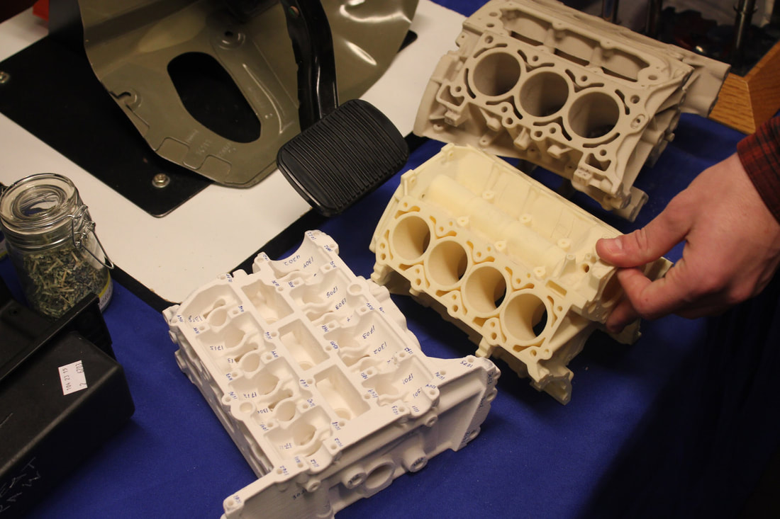
In an earlier blog post, we discussed 3D Printing and product design and how prototyping can play an important role in the field. You can also check out the 3D Printing Opportunities and Applications course that dives even deeper into 3D printing for prototyping and other fields.
Do you use prototyping to support your ideas? What types of prototypes do you often build, and for what reasons? Share your thoughts in the comments section.
Do you use prototyping to support your ideas? What types of prototypes do you often build, and for what reasons? Share your thoughts in the comments section.
By Tayseer Almattar, TforDesign Founder
Tayseer is the founder of TforDesign. He has a passion for learning design and making all learning digestible and exciting.
LinkedIn: https://www.linkedin.com/in/tayseer-almattar-design-innovation
LinkedIn: https://www.linkedin.com/in/tayseer-almattar-design-innovation
If you are reading this, you probably know that a SOLIDWORKS license is expensive! A standard commercial license of the 3D CAD tool might cost USD 2000+ / year. The professional and premium versions would cost even more going to USD 8,000/year. The cost makes lots of sense if you are a business taking advantage of it commercially, as the software can generate much more value than that.
However, suppose you are planning to use SOLIDWORKS for your own side projects at home or just looking to access the software for learning. In those cases, USD 2000+ is too much to be considered reasonable. So, let us look at the alternative, more affordable options going from the more general to the more specific. Specifically, we'll talk about the maker license, the EAA license, and the student license. For each, we will briefly address what it includes, how much it costs, how to get it, and the major limitations that come with it.
However, suppose you are planning to use SOLIDWORKS for your own side projects at home or just looking to access the software for learning. In those cases, USD 2000+ is too much to be considered reasonable. So, let us look at the alternative, more affordable options going from the more general to the more specific. Specifically, we'll talk about the maker license, the EAA license, and the student license. For each, we will briefly address what it includes, how much it costs, how to get it, and the major limitations that come with it.
Maker/Hobbyist License
SOLIDWORKS announced the maker license in 2021 for USD 99/year. It includes the primary standard 3D CAD tool that you will most likely use for maker or hobbyist projects. The maker license is the most generic version that is open to many regardless of their backgrounds.
- Cost: USD 99/year
- More information: https://discover.solidworks.com/makers
- Major limitation: not suitable for commercial use
Experimental Aircraft Association (EAA) Membership Benefit
EAA members get a 50% discount to access the SOLIDWORKS for makers license originally at USD 99/year. The trick is that you will need to be a member of the association, which costs USD 40/year. Thus, a membership and SOLIDWORKS cost a total of 89.5/year.
So, if you are interested in aviation, this would be a great option as you will also access many related resources. If not, this longer path can save you ten bucks.
So, if you are interested in aviation, this would be a great option as you will also access many related resources. If not, this longer path can save you ten bucks.
- Cost: USD 49.5/year for the maker license (+ USD 40 for membership)
- More information: https://www.eaa.org/eaa/eaa-membership/eaa-member-benefits/solidworks-resource-center/eaa-solidworks-standard
- Major limitation: Not suitable for commercial use

Student License
Students who are enrolled in academic institutions have their own licenses. The student version is equivalent to the Premium commercial version, which includes more features than the maker license. Those include simulation standard, CAM tools, PV 360 for rendering, and more.
- Cost: USD 99/year
- More information: https://www.solidworks.com/product/students
- Major limitations:
- Not suitable for commercial use
- Only available for students who are enrolled in an academic institution
So, here you have it. Those are your main options to easily access SOLIDWORKS if you are an individual and looking to use the software for personal applications. This also includes accessing the software to learn it and gain professional certifications.
Other than the major options listed above. Some other organizations might be able to provide free access to the software to their members. Those can include private and public organizations like universities. There is no comprehensive list for those. However, so it's something you will mostly like to find out about with the perks. So, suppose you are a member of an organization that is affiliated with SOLIDWORKS, you should ask around in case you can access the software through them.
Now that you have access to the software, it is crucial that you have the skills to capitalize on it as quickly as possible. For that, you can check out the bundle of online SOLIDWORKS 3D modeling programs at the TforDesign School.

By Tayseer Almattar, TforDesign Founder
Tayseer is the founder of TforDesign. He has a passion for learning design and making all learning digestible and exciting.
LinkedIn: https://www.linkedin.com/in/tayseer-almattar-design-innovation
LinkedIn: https://www.linkedin.com/in/tayseer-almattar-design-innovation
3D models need to be moved around and oriented to do various tasks like viewing them properly, adding features, taking measurements, etc. Therefore, proper model orientation is essential and should be easily accessible. This is where the Orientation Dialogue Box comes to our help which can be accessed by simply pressing Space Bar or from the top of the canvas. It lets us select from standard views like Front, Right, Top, Isometric views, activate View Selector, and use viewports. Most of the time, we need more orientations for ease of navigation. For example, maybe we need a close-up on a cut, or an angle not included in the default views. For this, we can create Custom Views
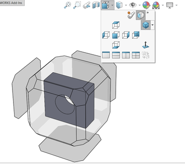
Creating Custom Views
Custom views are views that are added and saved in the Orientation Dialogue Box as per our needs. They come in handy when we want a specific orientation and zoom level of the model at any time.
To create a custom view, click on the New View icon in the Orientation Dialogue Box (as shown in the below image) > Name the view in Named View pop-up > Click Ok. This will capture the current orientation and zoom level of the model. The named view is now added in the Orientation Dialogue Box and can be accessed by pressing the space bar and selecting it from the list.
To create a custom view, click on the New View icon in the Orientation Dialogue Box (as shown in the below image) > Name the view in Named View pop-up > Click Ok. This will capture the current orientation and zoom level of the model. The named view is now added in the Orientation Dialogue Box and can be accessed by pressing the space bar and selecting it from the list.
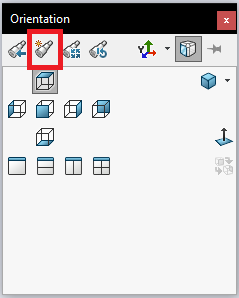
Adding a Custom View to all SOLIDWORKS Documents
Recreating the same custom view orientations in each SOLIDWORKS document is time-consuming. To save time, you have to save them. Open the Orientation Dialogue Box, hover over a custom view from the list and click on the Save icon. This will make these views available for all the parts, assemblies, and drawings.
If you are looking to learn SOLIDWORKS with a bundle of learning support services, make sure to check out the TforDesign school online SOLIDWORKS 3D modeling courses.
If you are looking to learn SOLIDWORKS with a bundle of learning support services, make sure to check out the TforDesign school online SOLIDWORKS 3D modeling courses.
By Mohsina Zafar, Technical Lead at TforDesign
Mohsina is a Mechatronics engineer who is passionate about 3D design and artificial intelligence. She specializes in SOLIDWORKS 3D CAD and loves to help students solve their SOLIDWORKS problems.
LinkedIn: https://www.linkedin.com/in/mohsina-zafar/
LinkedIn: https://www.linkedin.com/in/mohsina-zafar/
In this post, we will try to make sense of what is finite element analysis (FEA) and how it works without getting into talking about equations or much technical terms. SOLIDWORKS Simulation (and other software) uses FEA to solve designs. Thus, knowing a bit of background about FEA will help us understand many of the settings to optimize our results.
To explain FEA in simple terms, we can try simplifying FEA with a story of the progression of the elements from one dimension to 3 dimensions.
To explain FEA in simple terms, we can try simplifying FEA with a story of the progression of the elements from one dimension to 3 dimensions.
One Dimensional Beams:
It all started with the classic problem of a beam. The beam is fixed on a wall from one end, and there is a force on the other end. Experts came together and made up an equation to find the deflection at the outer end. What the equation looked like is none of our concern for now, so we can just call it THE EQUATION.
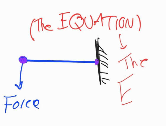
Here is what concerns us: To be able to calculate the deflection on the outer end, we had to know beforehand what the deflection is on the inner end connected to the wall. In this classic beam case, we know that the inner end is fixed to a wall. Thus, there is no deflection, or the deflection is zero. With that known to us, we can apply the equation and find the deflection.
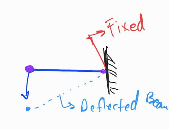
Now the question is: What if we want to know the deflection in the middle of the beam?
To find this, we can split the beam into two and redo the whole calculation. We can start with the first half, in one end we know the deflection is zero, so we can apply THE EQUATION to find the deflection at the end of the first half. Then, we can move to the second half and apply the same equation. Again, we already know the deflection in one end because we just calculated It, then the equation will give us the other end.
To find this, we can split the beam into two and redo the whole calculation. We can start with the first half, in one end we know the deflection is zero, so we can apply THE EQUATION to find the deflection at the end of the first half. Then, we can move to the second half and apply the same equation. Again, we already know the deflection in one end because we just calculated It, then the equation will give us the other end.
Finite Element Analysis is dividing a structure into a smaller, finite number of elements which we can analyze one by one, then putting all those elements together gives us an understanding of the whole structure.
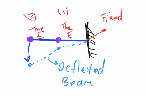
What if we want to know the deflection in every quarter of the beam?
In this case, we can simply redo the same procedure the same way, splitting the beam into four parts. We can go the same approach every tenth of the beam, every twentieth, and so on.
In this case, we can simply redo the same procedure the same way, splitting the beam into four parts. We can go the same approach every tenth of the beam, every twentieth, and so on.
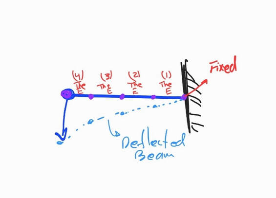
Now let us stop here for a second to name things, we can all those little beam divisions: ELEMENTS,, at the end of each element, there are points that we can call NODES.
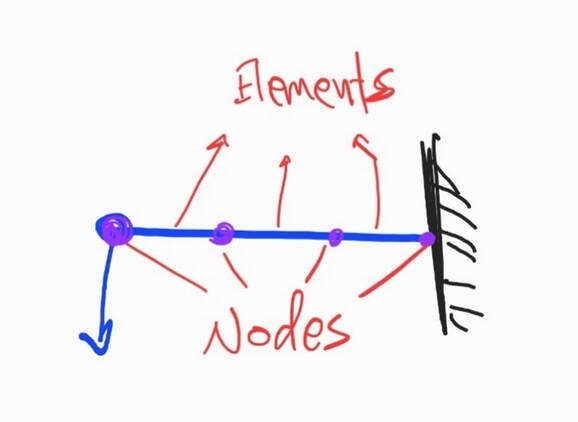
This approach we just used or described in analyzing our beam is Finite Element Analysis.
It is dividing a structure into a smaller, finite number of elements which we can analyze one by one, then putting all those elements together gives us an understanding of the whole structure.
It is dividing a structure into a smaller, finite number of elements which we can analyze one by one, then putting all those elements together gives us an understanding of the whole structure.
Two Dimensional Shells / Surfaces:
Just now, we were looking at a straight beam, which we were able to split into straight little elements of lines and nodes.
The next step would be to go to two dimensions. We can call those shells or sheets. A shell is anything that is relatively thin and of uniform thickness. Those include the common structures of sheet metals.
The next step would be to go to two dimensions. We can call those shells or sheets. A shell is anything that is relatively thin and of uniform thickness. Those include the common structures of sheet metals.
Figure 1. Stools made out of sheet metals
Sheet metals can take many different shapes and forms. Also, unlike one-dimensional beams, there is no ‘THE EQUATION’ to solve for deflections on complex formations.
To go around this, we can simply split the whole sheet into many nodes and lines. However, now that we are working in 2 dimensions, our elements can’t be a line. So, we can switch the elements into something like a triangle.
To go around this, we can simply split the whole sheet into many nodes and lines. However, now that we are working in 2 dimensions, our elements can’t be a line. So, we can switch the elements into something like a triangle.
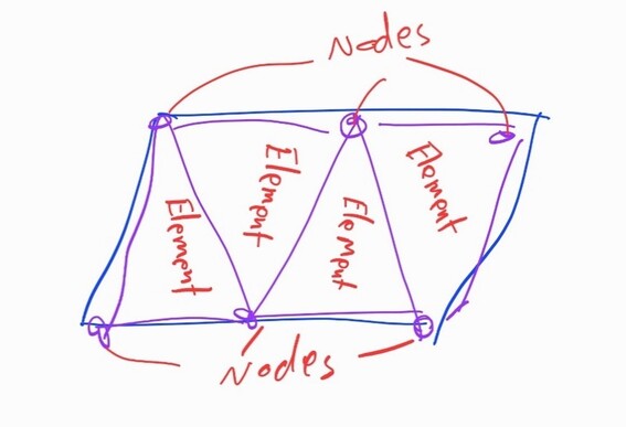
Now, we can split our sheet into little triangular elements. Each has three little lines and three nodes. Just like how we started with beams, we must know the actual solution values somewhere in the design because it is fixed or restrained to something else. From there, we solve for each little line and each little element until we can solve for the whole model. Basically, we transformed the whole shell into many small one-dimensional beams. The collection of all the elements together is called Mesh.
The more elements we have, the more accurate our results will be, but also the more calculations we will have to do.
The more elements we have, the more accurate our results will be, but also the more calculations we will have to do.
3-Dimensional Solid Objects:
At this point, we can jump into 3-Dimensional objects. which can be complex-looking turbines, gears, casings, consumer products, etc. We can refer to those as SOLIDS.

Many of the artifacts around us have irregular shapes
As solids can take many different shapes and forms, there is no ‘THE EQUATION’ for all kinds of irregular shapes. However, that is not a problem because we can just split the whole thing into small elements to end up with a bunch of nodes and lines. Our element shape this time will have to be 3-dimensional shape, like a Tetrahedral, which is the shape of elements used in a software like SOLIDWORKS.
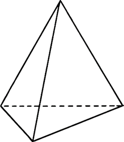
As always, with one location of the design is known to us, so we can use THE EQUATION to solve what is happening in the next nodes, and move from there to the rest of the model. Generally speaking, the more elements we have, the more nodes and lines we have, the more accurate our results can be, and the more work we will have to do to solve it.
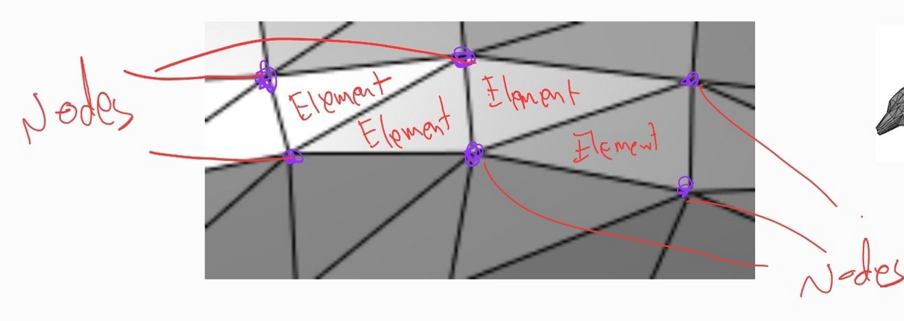
Summary:
In a nutshell, Finite Element Analysis is the idea of splitting any model into smaller elements that we can solve one at a time, then putting all those elements together can give us a good understanding of what is happening in the whole model.
The power of FEA is that it enables us to understand and simulate how a specific design reacts to different conditions regardless of how complex the design is. Throughout this post, we gave a bit of focus to analyzing deflections. However, the same approach applies to analyzing and understanding many other parameters like stress distribution, the factor of safety distribution, etc.
This post does not represent a factual background on Finite Element Analysis and should not be taken as such. Rather, you can take it as a way to simplify our understanding of what Finite Element Analysis is all about.
If you are looking to dive into the use of an FEA-based simulation tool like SOLIDWORKS simulation, you can check out SOLIDWORKS Simulation Associate course.

By Tayseer Almattar, TforDesign Founder
Tayseer is the founder of TforDesign. He has a passion for learning design and making all learning digestible and exciting.
LinkedIn: https://www.linkedin.com/in/tayseer-almattar-design-innovation
LinkedIn: https://www.linkedin.com/in/tayseer-almattar-design-innovation
When asking about FEA simulations, you will likely find two groups of people: one calling it straightforward and easy and the other calling it complex and challenging. You will also find lots of young people sharing colored images and more experienced people talking equations and strange terms. What is behind all that? [it is not a cross-generational thing, at least I hope]
Most of that comes from the introduction of software simulation tools. There is no doubt that Simulation tools, including SOLIDWORKS, Ansys, and others, brought in tremendous benefits and enhancements to simulation. However, they made simulation look super easy. But is it?
Most of that comes from the introduction of software simulation tools. There is no doubt that Simulation tools, including SOLIDWORKS, Ansys, and others, brought in tremendous benefits and enhancements to simulation. However, they made simulation look super easy. But is it?
Beautiful Simulation Animation
So, let us try to break that further down to figure out some of the issues with the simulation software.
First, one area to clarify is that most simulation studies are applied by following a similar overall procedure. You can check our previous blog on 8 steps to conducting FEA static studies for more information. Now, we did a simple study, let us talk about the complications. This blog will discuss the meaning behind the results, results verifications, and the overwhelming available options.
What Do the Results Mean to Start With?
Simulation software are famous for their colorful plots, usually ranging from red to blue, and accompanied by numbers. While it is easy to get numbers and plots, the more important question would be: what do those numbers even mean? Von Mises, stresses, strains, the factor of safety, stiffness, etc.
More importantly, what do those numbers mean for us specifically in whatever project we are working on? How can they be used to drive/guide meaningful design iterations?
Answering those questions would often require more in-depth knowledge and experience on topics that go beyond the apparent software application and into principles of design and mechanics of materials.
Verdict:
- Getting numbers and colorful plots: Easy.
- Being able to understand those numbers and reflect them on our projects: Not as easy.
Getting attractive and colorful plots can be pretty exciting when you start with simulation, but there is often more than meets the eye.
How Do You Know the Software Gave You Correct Results?
Perhaps one frequent and more challenging question you can get working with simulation is: How do you know you got usable/correct results?
Simulation software nowadays are very capable; they are also growing rapidly. However, they are by no means a complete, accurate tool. Issues in results can be caused by anything from setting the simulation conditions wrong, software deficiency, to issues with our input to the software.
Being able to spot those errors would often require both experience and depth of engineering knowledge. Some methods used to help can range from quickly spotting nonsensical results to benchmarking with hand calculations or other means.
Verdict:
- Getting results: Easy
- Verifying the results: Not as easy
All the Options Out There!
As simulation tools grow, so does the number of options they provide to help you get optimal results for your usage. Those include more variety in conditions setting, more options in refining the mesh, more plots, etc. Being able to navigate all those options to produce a usable study can range in difficulty according to the complexity of the study.
The complexity comes from the number of options and having to understand what each option means in an absolute sense and what the option means to the specific study you are working in. For example, meshing refinement has several options, from setting a global mesh density to auto-adaptive meshing to manually adjusting the mesh in different areas of the design. Knowing about those options is the easy part compared to uniquely applying them to best fit each project.
Verdict:
- Running a study: Easy
- Running an optimized study: Not as easy
So, is Simulation Easy or Complex?
All the writing above might have made you more confused than not. Is simulation easy or complex?
The reality is simulation is just like other expanding fields of study. It has a surface, but beneath that exists a great depth. The deeper you go, the more complex things can get. Thus, do not be surprised when you meet people spending 20+ years using simulation and are still learning.
While software applications came as great enablers for simulation, they can give some a false sense of knowledge, neglecting the depth of the field. Getting attractive and colorful plots can be pretty exciting when you start with simulation, but there is often more than meets the eye.
Should I Learn Simulation?
In terms of software application, a structured course can give you the best value for your time. You can check out the TforDesign SOLIDWORKS Simulation Associate course. This will build you a strong foundation in the practical software application using SOLIDWORKS.
Another part is to equip yourself with a theoretical background in Mechanics of Materials and Finite Elements Analysis. Both fields are well-established in academia. Thus, browsing academic resources can give you the best value.
When pursuing both directions, it is essential to know that growing in the area can take lots of time and patience.
Are you a user of simulation tools? How was/is your experience? Let us know in the comment section.
When pursuing both directions, it is essential to know that growing in the area can take lots of time and patience.
Are you a user of simulation tools? How was/is your experience? Let us know in the comment section.

By Tayseer Almattar, TforDesign Founder
Tayseer is the founder of TforDesign. He has a passion for learning design and making all learning digestible and exciting.
LinkedIn: https://www.linkedin.com/in/tayseer-almattar-design-innovation
LinkedIn: https://www.linkedin.com/in/tayseer-almattar-design-innovation
Author
The following blogs are written by TforDesign team and community members.
Categories
All
3D Printing
Design Innovation
Simulation
SOLIDWORKS 3D Modeling
 RSS Feed